


28 en FAS-420-TM | FAS-420-TM-R | FAS-420-TM-RVB
F.01U.088.879 | 3.0 | 2009.07 Bosch Sicherheitssysteme GmbH
1. First, clearly mark the fixing points on the installation position provided on the
equipment. To guarantee a safe and low-vibration hold, the housing base must be
secured with four screws (
∅ max. 4 mm).
2. Fix the housing base to the surface by means of four screws in accordance with the
mounting type. Make sure that the housing base is not fixed under mechanical tension
and that the screws are not tightened too much. Otherwise, the device might be
damaged or undesirable secondary noise may arise.
3. Using a screwdriver, carefully punch out the required cable entries from the housing
base.
4. Carefully fit the cable entry/entries as required with M20 or M25 glands (1 x M25 and
2 x M20 included in the delivery) by inserting them into the corresponding cable entry/
entries.
5. Punch out the cable entries using a sharp object.
Caution: Do not cut the cable entries with a knife!
6. Feed the connection cable(s) (max. cable cross section 2.5 mm²) through the suitable
cable entry/entries into the device and cut to the required length inside the device.
7. Wire the unit according to the connection information described below.
Connecting the FAS-420-TM Series
i
NOTICE!
- When selecting the installation location, it must be ensured that the unit displays are
easily visible.
- Remember when planning that the unit fans generate a noise level of approx. 40 dB(A).
- The air outlet on the unit must not be obstructed. The distance between the air outlet
and adjacent objects, e.g. a wall, has to be at least 10 cm.
- The aspirating smoke detector can be installed with the suction device upwards or
downwards (to do this, the detection unit cover must be rotated through 180°). If the
aspiration pipe points downwards, make sure no impurities enter the air-return pipe
which then points upwards.
i
NOTICE!
The units are usually connected to an additional power supply. When connecting to a Bosch
fire panel LSN improved version, the voltage is supplied via the AUX outputs of the battery
charger module. Alternatively, an external mains unit (e.g. FPP-5000 or UEV 1000) can be
used.
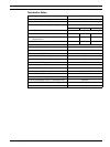
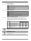
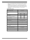
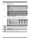
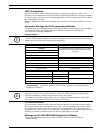
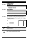
Figure 4, Page 4
Designation Cable Function
V+ Red Additional power supply, incoming
V- Black
V+ Red Additional power supply, outgoing
V- Black
a1- White LSN a, incoming
b1+ Yellow LSN b, incoming
a2- White LSN a, outgoing
b2+ Yellow LSN b, outgoing
Shield - Shield wire
Data+ - Data line connection for digital external detector alarm
display*
Data- -
*Digital external detector alarm displays for the FAS-420-TM Series must be ordered
separately.