


FAS-420-TM | FAS-420-TM-R | FAS-420-TM-RVB en 27
Bosch Sicherheitssysteme GmbH F.01U.088.879 | 3.0 | 2009.07
System Overview
Setting the Detector Address
Installing the Unit
Figure 1, Page 3 FAS-420-TM Series Connections
1 Connection for aspiration pipe
2 Connection for air-return pipe
3 Pre-punched M 25 cable entries for connection to fire panel or power supply (input/
output)
4 Pre-punched M 20 cable entries for connection to fire panel or power supply (input/
output)
Figure 2, Page 3 FAS-420-TM Series Displays
1 Operating LED
2 Main alarm LED
3 Pre-alarm LED
4 Fault LED
5Infrared port
6 Fire source identification displays for areas A-E
7 10-segment smoke level display
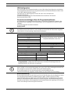
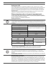
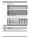
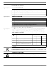
Figure 3, Page 3 The aspirating smoke detector's address is set using the 8-pin DIP switches on the printed
circuit board and a suitable sharp object. The default address is "0" (all DIP switches set to
"off"). The DIP switch settings for all approved addresses are listed on pages 5-6 (0 = off,
1=on).
Address
(A)
Operating mode Network structure
Loop Stub T-tap
0 Automatic address assignment in "improved
version" LSN mode
XX-
1 to 254 Manual address assignment in "improved
version" LSN mode
XXX
255 = CL Automatic address assignment in "classic"
LSN mode (address range: max. 127)
XX-
x = possible
- = not possible
i
NOTICE!
It is not permitted to use different operating modes in one loop/stub/T-tap next to each other.
!
WARNING!
The equipment may only be installed by authorized and qualified personnel!
Switch off the unit before carrying out any connection work!