


RAID Subsystem DVA-12T | Installation Manual Subsystem Connection and Operation | en 29
Bosch Security Systems F.01U.027.798 | V1 | 2006.06
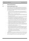
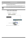
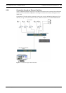
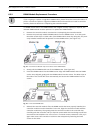
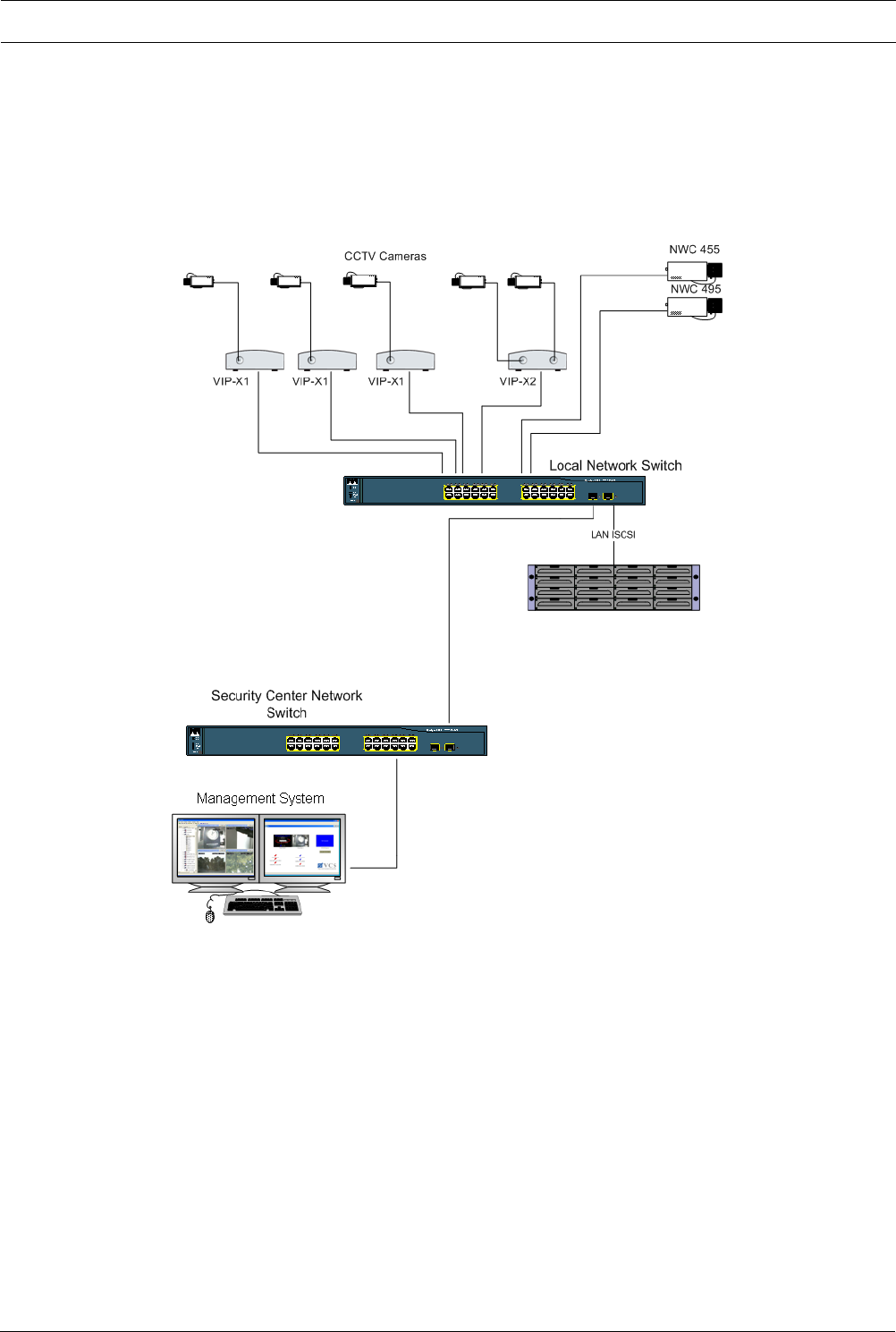
5.2.2 Connection through an Ethernet Switches
In the configuration shown in Figure 5.2 all codecs and cameras are connected via an Ethernet
Switch. This is a standard configuration for using IP cameras and codecs sharing the same
iSCSI drive.
A maximum of 31 units can be connected. In this case, a unit is defined by having one (1) IP
address, so e.g. a unit can be either a VIP X1, a Dinion IP camera or one VIP X1600 module.
Fig. 5.2 Connection through an Ethernet Switch