


D268, D269 Operation and Installation Manual
74-04758-000-H Page 8 Copyright © 2001 Radionics
D268, D269
Installation
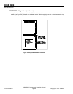
D268 Module Installation
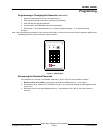
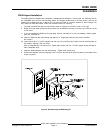
Mounting the D268
The D268 Independent Zone Control Module is suitable for installation in a D8103 Enclosure or a D8108A Attack
Resistant Enclosure. Both enclosures available for UL certified Local and Central Station Grade A or B, and
Police connected burglar alarm applications. Align the D268 Module with any of the four mounting locations, and
fasten the module in place with the three mounting screws provided.
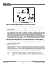
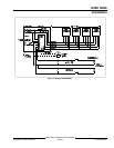
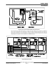
Wiring the D268
Three wires are used to connect the D268 Module to the panel, +12 VDC, common, and zone or point input.
These wires are connected to a 10-position terminal block on the D268 Module (see Figure 4).
The D268 output (terminal 5) can be connected to a 1k Ω zone or point of a Radionics control/communicator. The
zone or point input requires only a single wire from the D268 that connects to its positive terminal. No terminating
resistor is required.
D268 Protective Zones
D268 sensor loops function independently, and are similar to the loops on the panel. Each sensor loop is
supervised with a Radionics model 105BL 1k Ω end-of-line resistor supplied with the module (see Figure 4).
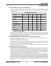
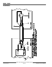
Protected wiring (Figure 5) may be required for applications where the D268 sub-zone cable is exposed. You can
use 22 AWG (minimum) wire in place of the tin copper shield braid (Figure 5:, Note 2), and rigid conduit or
electrical metallic tubing can be used in place of the PVC tubing (Note 3). All splice boxes must be tampered.
Dry contact sensing devices may be connected in series (normally-closed) or in parallel (normally open) to each
sensor loop. Each loop can detect open circuit, closed circuit, and normal circuit conditions. For complete
information, see Using the D268 Module with the D8112 and Using the D268 with the D7112/D9112 in this
manual.
Optional Alarm Device Wiring
An optional alarm device, such as a bell, can be installed to annunciate alarms associated with the D268/D269.
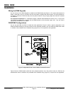
Figure 4 shows the wiring of the optional device from the D268 Module to the panel. A Radionics model D136
Relay must be installed in the K1 socket of the D268 Module (see Figure 2) to operate this optional device. The
socket is designed so the relay can be inserted in either the top or bottom positions. Insert the relay with the three
legs facing away from C3. If a fault is detected on a D268 loop, the on board form C relay is activated. The relay
is latched until you enter the passcode. See the appropriate Operation and Installation Manual for further details
on the programming and operation of the Alarm Output.
D268 Jumpers
The D268 Module contains two movable jumpers. The location of these jumpers is shown in Figure 2. Jumper
J1 is used to enable and disable the passcode change function from a D269 Keypad. With the jumper plug
installed in the “A” (COMB CHG) position, you can change the passcode. If the jumper plug is installed in the “B”
(NO) position, you cannot change the passcode.
Jumper J2 enables the control/communicator to receive opening and closing reports from the D268. When the
jumper plug is in the “B” (OP/CL) position, opening and closing reports are sent . When the jumper plug is in the
“A” (NO) position, opening and closing reports are not sent.
D268 LED: The red LED on the D268 Module is for manufacturing test purposes only.