


6 en | MIC 500 Series Camera Quick Start Guide MIC Series 500 Camera
F.01U.173.601 | 2.0 | 2010.11 User’s Manual Bosch Security Systems, Inc.
A standard female BNC connector provides the composite video output from the MIC 500
Series camera.
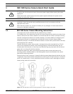
Telemetry Connections
The MIC 500 Series camera can be daisy-chained in a multi-drop configuration, the last or
furthest camera in the chain should be typically terminated with a 120 Ω resistor placed
across the cameras receiving pair.
1.3 Commissioning the MIC 500 Series Camera
The MIC 500 Series camera provides twin protocol support with a single software pack.
Switching between the installed protocols is easily done using cam-set or the on screen menu
function. Three protocol packs are available: Forward vision (FV)/ Bosch, FV/Pelco and FV/
VCL.
All MIC 500 Series cameras are supplied set to address 1 and initially loaded with the FV /
Bosch protocol pack. The available protocol packs are provided on the CD and can be loaded
onto the camera using cam-set.
To use the MIC Series Universal Camera Setup software (cam-set), connect the MIC 500
Series camera power supply (HD4 or HD5) to a PC using either the MIC-USB485CVTR, an
RS485 to USB signal converter, or for older PCs with a serial port, a suitable RS232 to RS485
converter can be used. Please refer to the Help and Instruction file in cam-set for further
details.
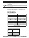
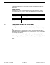
Telemetry
Signal Function Telemetry Signal Name HD4 or HD5
RS485+ to camera RxB Pin 1
RS485– to camera RxA Pin 2
0v from control room GND Pin 3
RS485– to control room TxA Pin 4
RS485+ to control room TxB Pin 5