


MIC Series 500 Camera MIC 500 Series Camera Quick Start Guide | en 5
Bosch Security Systems, Inc. User’s Manual F.01U.173.601 | 2.0 | 2010.11
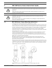
The MIC 500 Series camera has a security attachment point for attaching to a safety chain
(not supplied), which in turn should be attached to a secure part of the structure during
installation or removal.
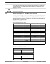
1.2 Safety Earthing of the MIC 500 Series Camera
The electronics and housing of the MIC 500 Series camera are electrically isolated; however,
the housing should be safety earthed regardless. This safety earth should be a bonding
connection, such as one of the securing bolts, to the outside case of the camera. The camera
should be earthed at one point only to prevent earth loops and thus hum bars appearing on
the camera picture in the control room.
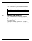
Shielded Composite Cable Connections
Note: all connections must be made.
Mains Power and Video Connections
WARNING!
Use caution when installing the MIC 500 Series camera. Follow common sense precautions
such as fitting a safety chain.
Composite Cable Wire Color Function MIC PSU Terminal Block PCB Marking
Red AC supply HD3-1 Power
Green AC supply return HD3-2 Power
White RX + Hd3-3 RxB
Yellow Rx - HD3-4 RxA
Drain Wire Ground HD3-5 GND
Blue Tx - HD3-6 TxA
Violet Tx + HD3-7 TxB
Coax Core Video HD3-8 Video
Coax Screen Video return HD3-9 Vid 0V
Black (optional) Tamper switch HD3-10 Tamp Sw
Orange (optional) Wash drive HD3-11 Wash
Brown Heater+ HD6-1
Gray
Heater-
1
HD6-2
1. Please refer to the MIC Series Power Supply Manual for details on connecting MIC 500 Series cameras with
heaters and other auxiliary equipment.
Mains
Live HD1-1
Neutral HD1-2
Earth Connection Already made
Video
Video BNC CN1 Connection
Core Video to Control Room
Screen Video GND to Control Room