


12 5
Your installer will advise you of any actions you should take to
ensure that the satisfactory and efficient operation of the heating
and hot water systems connected to the boiler are maintained.
CENTRAL HEATING SYSTEM
During the first few hours of operation of the central heating
system, check that all radiators are being heated at an even rate.
Should the upper area of a radiator be at a lower temperature than the
base of the radiator, it should be vented by releasing air through the
venting screw at the top of each radiator. Make sure your installer
shows you how to carry out the operation. On a sealed system repeated
venting will reduce the quantity of water in the system and this must be
replenished for safe and satisfactory operation of the appliance. Should
water leaks be found in the system or excessive venting be required from
any radiator, a service engineer should be contacted and the system
corrected.
CLEARANCES
Compartment With Ventilation
Your installer will have provided adequate space around the
appliance for safety and servicing. This space must not be restricted
by the addition of cupboard shelves etc. closer to the appliance. The
following minimum clearances are required.
Compartment With No Ventilation
Your installer will have provided adequate space around the
appliance for safety and servicing. This space must not be restricted
by the addition of cupboard shelves etc. closer to the appliance.
Flammable objects must not be stored in this type of compartment.
The following minimum clearances are required.
* The clearance at the front is to be a removable panel e.g. a door. A clearance of 600mm
should be allowed with the door open.
GENERAL NOTES
98
OPERATION OF
CONTROLS
More than 30% of all calls made to our contact centre reporting
appliance faults or breakdowns prove to be false alarms, as there is often
a simple explanation for the apparent malfunction.
So, to help you save time and money – not to mention frustration
and inconvenience – please refer to the General Information, Notes and
Lighting Instructions ensuring all controls are set correctly.
If, after following the instructions the appliance still fails to operate
correctly call the Worcester Contact Centre. Arrangements will be made
for an engineer to call as soon as possible.
NOTE: No sealed components should be adjusted. Failure to
comply with this will invalidate any warranty and will be hazardous to
the user.
CALL-OUT CHARGES
All of our field service engineers are factory trained.
If you request a visit from an engineer and your appliance has been
installed within the last 12 months, no charge will be made for parts
and/or labour, providing:
•
The appliance was commissioned correctly on installation.
•
An appliance fault is found and the appliance has been installed
within the past 12 months.
A call-out charge will be made where:
•
The appliance has been installed for over 12 months, or
•
Our Field Service Engineer finds no fault with the appliance (see
note), or
•
The cause of breakdown is with other parts of your
plumbing/heating system, or with equipment not supplied by Worcester.
NOTE: Invoices for attendance and/or repair work carried out on
your appliance by any third party will not be accepted.
APPLIANCE FAILS TO
OPERATE
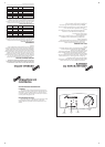
Fig. 1. Controls.
BOILER HEATING TEMPERATURE
CONTROL
The position of this control will determine the temperature of
the water delivered from the appliance between the start of the dial as
indicated thus ' ' and the fully on position i.e. when the control is
turned fully clockwise. When the knob is turned fully anti-clockwise
to the ‘O’ position the appliance is off.
BOILER RESET BUTTON
If the lockout light is on or flashing, turn the temperature control
fully anticlockwise to the 'O' position and back on again. If the
appliance still fails to operate then contact Worcester Bosch or your
installer.
Boiler
demand
Temperature
control
9/14CBi 14/19CBi 19/24CBi
Left-hand side 5 5 5
Right-hand side 5 5 5
In Front 600 600 600
Above (Rear Only Flue) 30 30 30
Above
(Flue Turret) 180 180 180
Below 200 200 200
9/14CBi 14/19CBi 19/24CBi
Left-hand side 105 105 105
Right-hand side 105 105 105
In Front* 340 340 340
Above (Rear Only Flue) 30 30 30
Above (Flue Turret) 180 180 180
Below 200 200 200
Burner
on
Lock-out