


6 720 607 057
Appliance details
11
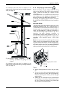
The appliance should be located as close to the point
of termination as possible. The maximum vent length is
26 feet (8 m) with one 90 degree elbow. Subtract 2½
feet from the total vent length for each additional 90°
elbow used (a maximum of three 90° elbows are
permitted in the total vent length), or subtract 1 ¼ feet
for every 45° elbow used. Horizontal sections of vent
must pitch ¼" for every foot of horizontal length and be
supported at 4 foot intervals with overhead hangers.
Note: Listed thimbles or collars are necessary to pass
through wall and ceiling partitions. If the vent system
passes through combustible areas where the vent
clearance requirements cannot be maintained, it is
permissible to chase straight sections of sealed 3 inch
single wall vent through 4 inch (or greater) Type-B vent.
The distance to combustibles using this chase
technique is 1 inch. Note: Type-B vent should never
be used as the actual exhaust vent system for the
appliance, as it is not gas tight.
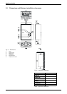
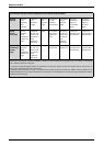
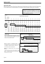
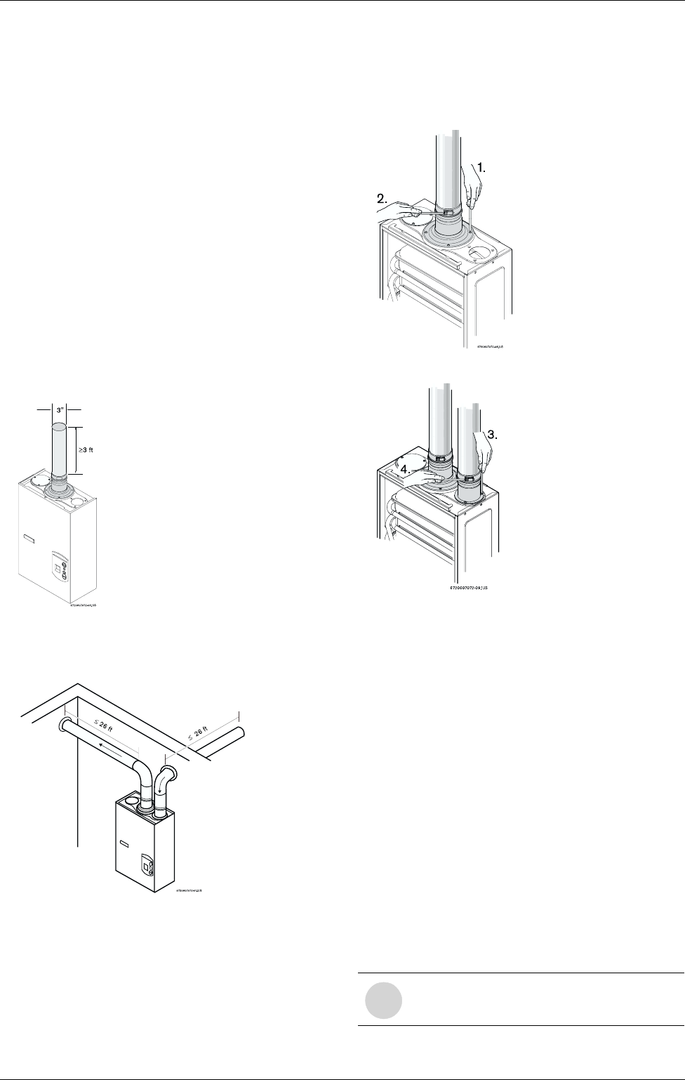
Minimum exhaust vent size and length
Fig. 8
Maximum exhaust vent and combustion air inlet
lengths
Fig. 9
Note: reduce 2½ ft for each 90° elbow used after the
first one, reduce 1 ¼ ft for each 45° elbow.
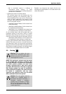
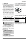
Vent Safety System
The 250 SX will shut down if inadequate exhaust
venting is detected or a lack of combustion air is
provided to the unit; see troubleshooting section on
page 24. See error code to confirm error, correct the
problem and then reset the heater before operating.
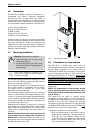
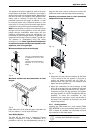
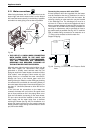
Attaching the exhaust and air inlet connection
adaptors to the top of the heater
Fig. 10
Fig. 11
B Attach the flue gas exhaust accessory (8 705 504
114) to the top of the unit (position 1) using the 4
screws and gasket provided, and fully insert 3"
stainless steel vent pipe into the accessory and
tighten the clamp (position 2).
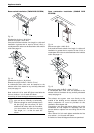
B Attach the combustion air inlet accessory (8 705
504 115) to the top of the unit (position 3) using the
3 screws and gasket provided, and fully insert 3"
combustion air pipe into the accessory and tighten
the clamp (position 4). NOTE: The appliance has the
possibility to mount the combustion air inlet
accessory on the top right or on the top left side of
the heater. The combustion air inlet that is not used
must be kept sealed.
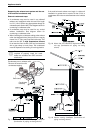
2.9.1 Venting options
Installing this water heater as a room sealed (TWIN
PIPE SYSTEM) is the recommended method. Contact
CEC or dealer for available vent termination kits and
vent materials for this water heater.
The use of a 90 degree elbow
is equivalent to 2 ½ ft in vent
length.
The use of 45 degree elbow is
equivalent to 1 ¼ ft in vent
length.
i
Exhaust venting shall be done with 3”
stainless steel (AL29-4C) vent pipe.