


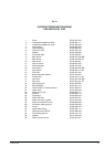

156 720 607 030
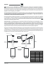
3. Poor thermocouple connection at the electromagnet
Note: Electromagnet is part #8707201012 located on the
right side of the gas valve behind the piezo push-button
assembly. Check the tightness of the thermocouple
connection nut at the electromagnet: The Electro-magnet
connection is a large aluminum 17mm hex head nut. The
thermocouple end is a 5 mm brass nut which screws into
the 17 mm nut. Tighten the thermocouple nut snugly but not
too tight.
4. Poor circuit connections at the ECO (overheat sensor)
or the flue gas safety device
Oxidation or looseness of the terminal connections can result
in millivolt current loss through the thermocouple safety
circuit. Clean terminals with very fine sand paper or an eraser
and reconnect leads.
5. Faulty ECO (part #8707206074)
If cleaning the terminals attached to the ECO did not fix the
problem, connect a jumper wire between the two wires and
try to relight the pilot. If the pilot flame now remains on,
replace the ECO. If the flame still goes out when the button
is released, the ECO is not defective. Go to next step.
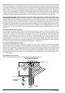
6. Faulty thermocouple (part #8707206074) or
electromagnet ) Unless these 2 parts are at least 8 to
10 years old, it is very unlikely that they are faulty.
Before testing, reconfirm that #2 is absolutely correct,
and that all connections are clean and tight.
To test the thermocouple, disconnect the thermocouple lead
at the ECO. Insert a multi-meter probe into the thermocouple
lead and attach or hold the other lead at the metal gas
valve (DC common). Light the pilot flame and hold button,
meter reading should be 24 mVDC or more. If the reading is
24 mVDC or more the thermocouple is good. To test the
electromagnet, re-connect the thermocouple lead to the
ECO, light pilot and hold button while taking a reading
between the ECO and flue gas sensor leads and the metal
gas valve (DC common). The reading should drop to 19
mVDC or less. If it does not, replace the electromagnet.
BURNERS DO NOT IGNITE WHEN HOT WATER IS TURNED
ON
1. Pilot is not on.
Light the pilot. See lighting instructions.
2. Cold incoming water connection made to wrong side
of heater
Make sure cold water inlet connection is on the right side of
heater when you are facing heater.
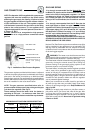
3. Water flow rate at hot water tap is too low.
Note: When the flow control knob is turned all the way
clockwise, the AquaStar models 125B require 1/2 gallon
per minute flow to activate the burners. This is a flow which
would fill a quart jar in 30 seconds. If the flow control knob
is turned fully counterclockwise, a flow rate of 1.1 gpm is
required to activate the burners.
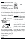
4. Cold water inlet filter on heater is dirty.
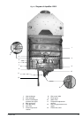
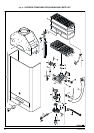
Remove filter and clean. This screen filter is located at the
inlet side of the water valve (fig. 13, #25). Check and clean
faucet aerators too.
PILOT LIGHT WILL NOT LIGHT
1. No gas to the AquaStar
A. Gas cock on gas line may not be open.
B. Gas valve button has not been moved to single flame
position ( ). Slide button to right to PILOT.
C. Gas regulator may be shut or damaged.
2. In-line AquaStar gas regulator jammed (usually on
LP gas)
Replace or unlock the regulator. Note: The regulator
furnished with the heater is designed for low gas pressure.
Excessive pressure will lock it up (propane only). Locking
usually happens if the gas pressure between the gas tank
(propane) and the water heater’s gas regulator has not been
reduced. See page 2 for recommended correct gas pressure.
To unlock a regulator, consult your gas supplier.
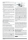
3. Pilot orifice clogged and/or air screen dirty, or pilot
gas filter is dirty.
Clogging of the pilot burner can be caused by dust and any
suspended matter contained in the ambient air.
As a result, the pilot flame is weakened and thus can no
longer heat the thermocouple sufficiently. For cleaning
purposes, the air filter screen is pulled off, washed and blown
out. The pilot orifice has likewise to be cleaned or exchanged.
4. Air in the Gas Line
Note: Normally this is a problem only at the time of initial
installation, after the pipes have been worked on, or after a
propane tank has been allowed to empty, or after the heater
has been shut down for a long time.
Bleed all the air trapped in the gas line. Because of the very
small pilot orifice (especially on LP gas models), bleeding
out all the air could take several minutes. Slide the gas
valve button to single flame position ( ) and depress this
button until all the air has escaped, and the gas has arrived.
During this process, press repeatedly on the piezo ignition
button until the pilot flame has ignited.
PILOT LIGHTS BUT FLAME GOES OUT WHEN BUTTON
IS RELEASED
1. Pilot push button was not pushed in far enough or
was not held in long enough
Once pilot flame has been lighted. Hold button pushed in
for at least 15 seconds to give time for the pilot flame to
properly heat the tip of the thermocouple.
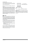
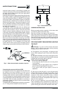
2. Pilot flame improperly aimed or is too weak so it is
not properly heating the tip of the thermocouple.
The Pilot flame should be a sharp blue flame and aimed at
the tip of the thermocouple so that it envelops 10 mm(3/8")
of the thermocouple tip. Pilot flame has to be properly aimed
at the thermocouple. See Fig 10.