


14 6 720 607 030
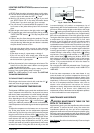
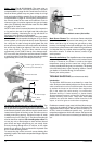
To clean the pilot burner and/ or the pilot orifice : Turn
off the gas at the unit. Remove the cover of the heater. To
do so, pull off the temperature adjustment knob and unscrew
and remove the plastic collar and unscrew the central screw
located at the bottom of the front cover. Pull main cover out
toward you and lift up and out . Pull the air screen off, wash
it and blow any lint off (See Fig 11). The pilot orifices should
also be cleaned or replaced. Do not enlarge the orifice. Do
not use any wire or sharp object to clean orifices. Natural
gas orifices are large enough that you can usually clean
them by blowing through them. LP orifices, on the other
hand, are too small to clean and should be replaced. See
#3 in Trouble Shooting Section.
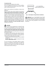
To access the pilot orifice, remove 2 screws holding pilot
assembly in place. Then loosen compression fittings to expose
pilot orifice.
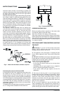
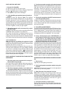
Fig. 10 - Characteristic Pilot Flame
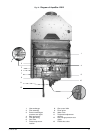
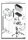
Water Valve (Part # 8707002649): The water valve on
this heater should be serviced periodically. Lubricate
component #23 on page 19 with a small amount of silicon,
faucet or lithium grease every two years to keep its o rings
fresh and pushrod sliding smoothly. Every 3-5 years replace
component #23 on page 19. The frequency will depend on
the mineral content of the water and conditions of use or
whenever signs of corrosion appear at the gas and water
valve joint. Periodically check that the water inlet filter (#25
on page 19) is clean as well.
NOTE: If water valve is removed, be sure to also inspect the
o ring seal on the end of the right hand side water pipe
before re-installing. Lubricating the o ring with lithium or
faucet and valve grease is recommended.
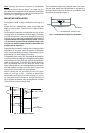
Pilot Flame: The pilot flame should burn with a clean sharp
blue flame and should resemble the diagram in Fig 10. If the
flame is yellow, or if the pilot knob has to remain depressed
for a long time in order to keep the pilot lighted, the pilot
burner and or the pilot burner orifice may need to be cleaned,
the orifice may need to be replaced, and or the air screen
may need cleaning. The pilot flame should envelop
approximately 10 mm (3/8") of the tip of the thermocouple.
If it is too small, the pilot burner must be cleaned. To obtain
a spark, the position of the Piezo igniter electrode should be
approximately 3 mm (1/8") from the pilot burner tip.
Main Burner Flames: The main burner flames should be
blue, with a more intense blue cone in the center core. Yellow
flames could be a sign of wrong size gas orifices or dirty
burners, or a blockage on the heat exchangers fins. If some
burners have yellow flames while others have good flames,
it is likely that dust, lint or spider webs have partially clogged
the burner venturis. To clean the burners, contact a gas
service person.
Mineral Scale Build-up: The AquaStar heater, when operated
at lower temperatures settings, does not accumulate mineral
build-up. If however, the heater is used at the higher
temperature settings and the water has a high mineral
content, periodic descaling may be necessary. The heating
coils should be flushed with a descaling solution. Consult
your dealer or Controlled Energy for instructions.
Consult your service person.
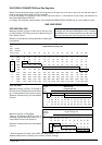
TROUBLE SHOOTING (see maintenance table)
Introduction
The AquaStar 125B burners are activated by a water flow
valve. Numerous water related problems can cause this water
valve to malfunction such as: Insufficient water flow volume
to activate the burners at its minimum flow requirement;
Dirt in the water flow valve causing it to malfunction;
Sediment build-up in faucet aerators, or shower heads;
Uneven pressures between cold and hot. (with single lever
faucets) Plumbing cross overs. These water flow related
problems can cause the heater to deliver less than its full
output, or to fail to ignite or to shut down completely.
Problems are stated in upper case, bold face. Most common
causes for the problems follow in order of likelihood. The
suggested solutions require that the cover be taken off. To
do this, remove incandescent particle tray, pull off the
temperature adjustment knob and unscrew and remove the
plastic collar. Pull main cover out toward you and lift up and
out.
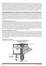
3mm
Correct gap between pilot
burner tip and electrode tip
Piezo Electrode
Air screen filter
10mm
3/8”
Piezo
Electrode
Thermocouple
Fig. 11 - Pilot burner with air screen/ pilot orifice
PILOT ORIFICE
AIR SCREEN