


24"
36"
24"
36"
24"
6"
24"
6"
32"
32"
8"
8"
12"
12"
32"
36"
3.000O
11.000O
4X 1.000O
4.000
4.0007.778
7.778
13.000
13.000
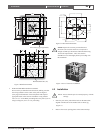
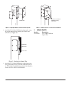
BASED ON A 11.00" B.C.
!
!
Bosch Security Systems
10 October 2003
EN
3
LTC9316/00P Instruction Manual Installation
Figure 2 Reinforcement Bars
Reinforcement bars (12)
PV4 Anchor jig (if applicable)
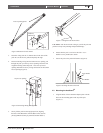
3. FOR ANCHOR BOLT INSTALLATIONS:
Pour concrete per manufacturer's directions, making sure that
the wiring conduit is in the center of the pad. See Figure 3
(next page) for dimensions of the bolt pattern and suspend
appropriate bolts in the concrete around the wiring conduit.
Leave 2" to 3" of the Bolts protruding above the pad. If you are
using leveling nuts, leave 4" to 6" protruding.
Figure 3 Anchor Bolt Dimensions
NOTE: Prepare the concrete per manufacturer's
directions. The concrete must have a compressive
strength of 3000 psi, and must be fabricated following
ACI318-89 requirements. Allow the concrete
foundation to cure thoroughly before proceeding with
the installation.
Figure 4 View of Concrete Foundation
1. Place the pole on the pad with the holes on the Base Plate
aligned with the bolts of the anchor bolts or anchor jig
(Figure 5).
2. Remove the access opening plates at the bottom and top.
NOTE: Be sure that the pole is oriented properly, with the
carriage.
4.2 Installation