


– 4 –
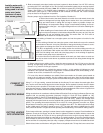
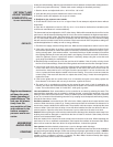
2. Bock recommends a two-pipe (suction and return) system for these heaters. Use 1/2" O.D. soft cop-
per tubing (5/8” O.D. soft copper on Sun Tec H pumps) and install a bypass plug on two-pipe system.
(See instructions packed with pump.) Note: Do not install a bypass plug if using a gravity (one-pipe)
s
ystem. (See Figure 1.) For multiple heater installations, run a separate suction and return line for
each heater. (See Figure 2.) If the combined lift and horizontal run exceeds 100’, install a booster
p
ump as close to the supply tank as possible.
B
ooster pumps may be obtained from Sun Tec Hydraulics, Rockford, Ill.
3. Return lines must be the same diameter as suction lines and extend close to the
bottom of storage tank but stop slightly above suction lines. Use a minimum of fit-
tings and make bends in tubing with as large a radius as possible. Always use
flared fittings, not compression fittings. If pipe is used instead of tubing, do not con-
nect the burner to the pipe – use copper tubing and form a coil before attaching tub-
ing to burner.
4
. When installing an oil water heater with an existing oil tank and lines, check exist-
ing line sizes and compare to instructions shipped with the pump to see if they are
adequate. Do not use existing lines if they are smaller than 1/2" O.D. tube on
Models 361E and 541E. Proceed as follows:
A. If existing oil heater has a one-pipe system, tee into the system to furnish oil to the
heater.
B. If the existing oil heater has a two-pipe system, check whether the return line extends
to the bottom of the tank. It may be preferable to change the existing oil heater to a one-
pipe system and change the return line to the suction line for the heater.
C. If (B) is not applicable, tee into the existing suction line and the existing return line to
supply oil to the heater. Both suction and return lines must extend to the bottom of the
tank, but if the tubing is too small and a two-stage pump is on the existing oil appliance,
the water heater pump may be starved for oil.
D. If return lines do not extend to the bottom of the tank, use check valves on each suc-
tion line as close to each burner as possible to prevent air from being drawn through the
return line.
E. Before teeing into an existing oil line, check the vacuum gauge in the 1/4" inlet port or the vent
opening. A single-stage pump should not exceed 12" hg vacuum and a two-stage pump should not
exceed 17" hg vacuum on two-pipe systems.
If the heater performs poorly, recheck the vacuum reading – a high reading will indicate too much
resistance. This could be caused by a clogged filter, a restricted shutoff valve, kinked tubing, an ob-
struction in the oil line, excessive lift or too long a run.
F. If none of the above installations are suitable, Bock recommends an oil booster pump located as
close to the oil supply as possible. Use the existing supply and return lines for the booster pump.
Change the existing unit to a one-pipe system and tee off the one pipe to supply oil to the water heater.
Using “L” or “A” type venting, connect the heater to the chimney. Do not reduce the smoke pipe diam-
eter; use the same size smoke pipe as the heater flue pipe. Run a separate connector from the heater
to the chimney where possible. If the heater must be joined to another oil appliance breaching before
going into the chimney
, enlarge the existing breaching to accommodate the extra volume of gases from
the heater. The entrance into the breaching should be at a 45
O
angle.
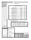
W
iring must be done in accordance with the National Electrical Code and local ordinances. Burners are
supplied with an operating thermostat (Honeywell L4103A or Carlin EZ-Temp 90000B on 72E,
Honeywell L4006A or Carlin EZ-T
emp 90000C or Carlin EZ-T
emp 90300B on the 73E through 361E,
and Honeywell L8100C or Carlin EZ-T
emp 90300B on 190E and 541E). Models 73E through 541E
equipped with Honeywell controls are also supplied with a separate L40801B high limit (see wiring dia
-
grams). The operating thermostat should be set at 120
O
F for normal domestic hot water use; higher
temperatures increase the risk of scalding. Do not set higher than 180
O
F. The differential control wheel
on the L4006 control (73E-361E) should be set to 15
O
F
.
The high limit control (L4080B used on 73E-
541E) should be set 20
O
F or higher above the operating thermostat setting.
The maximum setting is 200
O
F
.
Fill the heater with water, opening a hot water faucet to allow trapped air to escape. Check handholes for
tightness. Check the fuel supply and all fuel lines for tightness. Rotate the blower wheel to loosen the
pump shaft seal. Bleed air from the oil line by opening the bleed valve on the fuel pump.
Attach a small
plastic tube to the bleed valve fitting on pump and run to a gallon container
. Turn on the electricity and set
the thermostat so the burner motor runs. The heater will not ignite when the bleed valve is open. Bleed
the line until the oil is completely clear (not milky or opaque), transparent and free of air bubbles and froth.
Shut the bleed valve and the burner will ignite. Remove the plastic tube. To keep the burner control from
PUTTING HEATER
INTO OPERATION
Install a water soft-
ener if the heater is
b
eing used in a hard
w
ater area (water
hardness of more
than seven grains).
G
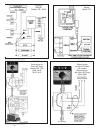
RAVITY SYSTEM
FIGURE 1
CONNECT TO
CHIMNEY
ELECTRIC WIRING
FIGURE 2