


– 3 –
Care must be taken to insure an adequate air supply for the water heater.
A
. Install equipment only where the water heater will have satisfactory combustion, proper venting,
and the maintenance of temperature at safe limits all around the unit under normal operating con-
ditions. Free circulation of air around the water heater is essential. If the air supply is inadequate,
introduce outside air. Any temperature above 90
°
F around the heater indicates a need for addi-
tional air (see NFPA 31 for air requirements).
B. In addition to air needed for combustion, air may be required for draft control; cooling off; controlling
d
ew point; heating; drying; oxidation or dilution; safety exhaust; odor control; and compressors.
C. Make sure air around the water heater is adequate for personnel comfort and working conditions.
D. Check for proper draft. Place a draft gauge in the chimney above the draft diverter. Drafts should
be at least -0.02" W. C. and less than -0.05” W.C. while the water heater is in operation.
U
nconfined space:
N
o additional combustion and ventilation air is required if the volume of the
space is greater than 50 cubic feet per 1,000 BTUH of the combined total input of all equipment in-
stalled in that space. Rooms leading directly to the space through openings which cannot be closed
are considered part of the unconfined space.
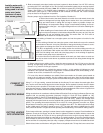
Confined space: When the unit will be installed in a space with a volume of less than 50 cubic feet
per 1,000 BTUH, the space must be vented at the floor for combustion air and at the ceiling for ven-
tilation. This air can be supplied from either inside or outside of the building as conditions allow (refer
to NFPA 31 or local codes).
A. Inside air supply: Provide two permanent openings; one within 12" of the top of the enclosure and
one within 12" of the bottom, leading directly to room(s) of sufficient volume so that the combined
volume of all the space meets the criteria for unconfined space. Each opening requires a mini-
mum free area of one (1) square inch (two square inches total) per 1,000 BTUH of the combined
total input of all equipment installed in the enclosure, but not less than 100 square inches.
B. Outside air supply: Provide two permanent openings; one within 12" of the top of the enclosure
and one within 12" of the bottom. These openings must lead directly to crawl and attic spaces
leading directly to the outside of the building.
1.
Leading directly to outside or through vertical ducts: Each opening (top and bottom)
requires a minimum free area of one (1) square inch (two square inches total) per 4,000 BTUH
of the combined total input of all equipment installed in the enclosure.
2.
Leading to the outside through horizontal ducts: Each opening (top and bottom) requires
a minimum free area of one (1) square inch (two square inches total) per 2,000 BTUH of the
combined total input of all equipment installed in the enclosure.
Louvers and grilles: In calculating the “free” area in Equipment Located in Confined Spaces,
consider the blocking effects of louvers, grilles, or screens protecting openings. The screens cannot
be smaller than one (1) inch of mesh. If the “free” area of a louver or grille is known, it should be
used in calculating the size opening required to provide the “free” area specified. If the design and
“free” area is not known, assume wood louvers have 20% to 25% “free” area, and metal louvers and
grilles 60% to 75%. Fix louvers and grilles in the open position or interlock with the equipment so
they are opening automatically during equipment operation.
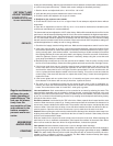
W
ATER PIPING:
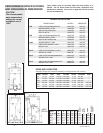
Models 72E, 73E, 190E, 241E and 361E have polysulfone dip tubes. When using
sweat fittings, do not apply heat to the nipples. Pipe hot and cold lines with a union and valve on
each line.
If backflow preventers and pressure regulators are installed or if the heater is installed in a closed
system, allow for water expansion by installing either a thermal expansion valve or an expansion
tank in the system. Contact the local water supplier or plumbing inspector to correct the situation.
The Bock factory has installed the properly rated temperature and pressure (T&P) relief valve.
To prevent water damage when relief occurs, install a discharge line from the relief valve outlet to a
place for water disposal. Do not install reducing coupling or other restriction in the discharge line.
Arrange the line to allow complete drainage of both the relief valve and the discharge line. If the T&P
relief valve discharges periodically, service to the water system is required.
Do not place the shut-off valve between the relief valve and the water heater.
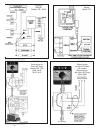
Check handholes for tightness.
1.
The operating thermostat and high limit are packed with the burner
. Mount the burner with bolts
provided. Burners are shipped with all settings at the approximate start point. Check inside the
combustion chamber to verify that the burner tube is not obstructed or protruding into the cham-
ber. Swing back the hinged transformer and rotate the blower wheel by hand a few turns to loosen
the pump seal.
COMBUSTION &
VENTILATION AIR
NOTE: All ducts
must have the same
cross sectional area
as the free area of
each opening to
which they connect.
The minimum side
dimension of a rec-
tangular duct must
be no smaller than
three (3) inches.
Caution: Operation
of exhaust fans, ven-
tilating systems,
power burners, in-
duced draft systems,
clothes dryers, or
fireplaces may cre-
ate conditions that
require special
attention to avoid
unsatisfactory oper-
ation of installed
equipment.
T&P RELIEF VALVE
ATTACH BURNER
& OIL LINES