


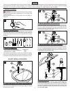
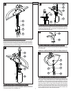
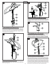
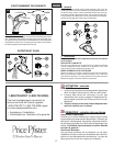
11 50/50 POP-UP INSTALLATION
Apply a small bead of plumber’s putty underneath the Flange (11A) and place
a ring of putty around Drain Opening (11B) of sink. Use PTFE plumber’s tape
to all threaded fi ttings according to manufacturer’s instructions. Insert Flange
(11A) into Drain Opening (11B). From underneath, insert Rubber Washer (11C)
and Friction Washer (11D) over the bottom of Flange (11A). Thread Locknut
(11E) until Rubber Washer (11C) seats securely inside Drain Opening (11B).
Thread Drain Body (11F) to bottom of Flange (11A). Hand tighten and adjust
the Drain Body so that the Ball Rod Opening (11G) faces the rear. Wrench
tighten Locknut (11E) and wipe excess putty.
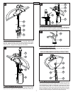
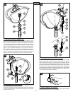
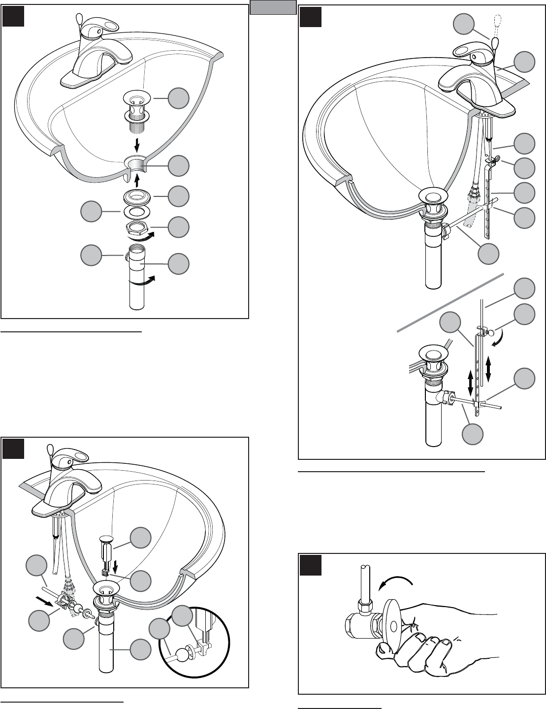
12 BALLROD ADJUSTMENT
Drop the Stopper (12A) into the Drain Body (12B) from the top with the Off-Set
(12C) facing rear. From below, insert the Ball Rod (12D) into the Ball Rod Opening
(12E) through the Stopper Hole (12F) and secure with the Nut (12G).
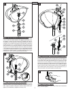
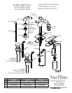
13 POP-UP ROD LINKAGE & ADJUSTMENT
Place one end of Spring Clip (13C) on end of Ball Rod (13B). Insert Ball Rod
(13B) across and through hole in Strap (13D). Secure other end of Spring Clip
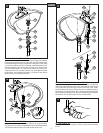
(13C). Insert bottom of Lift Rod (13A) into hole at top of Strap (13D). Tighten
with Thumb Screw (13E). Adjust Lift Rod (13A) function by adjusting location of
Thumb Screw (13E) along the Strap (13D), or by adjusting the hole in which Ball
Rod (13B) goes through Strap (13D). Be sure to leave enough space between
Lift Rod Knob (13F) and Spout Hub (13G) when Lift Rod is down.
14 UNIT START UP
Turn on hot and cold water supplies, and check for leaks above and below
the sink.
11
12
13
14
4
ENGLISH
11A
11C
11B
11E
11D
11F
11G
12A
12B
12C
12E
12D
12D
12G
12F
13A
13F
13A
13E
13E
13D
13D
13C
13C
13B
13B
13G