


724-746-5500 | blackbox.com
Page 20
724-746-5500 | blackbox.com
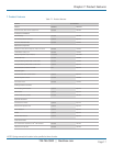
Chapter 8: Product Guide Specifications
ELECTRICAL SYSTEM
The electrical system must conform to National Electrical Code (NEC) requirements. In accordance with NEC Class II requirements,
the control circuit must be 24 volts AC wire, and control circuit wiring must not be smaller than 18 AWG. All wiring must be
neatly wrapped, or run in conduit, or cable trays, and routed in bundles. Each wire must end with a service loop and be securely
fastened by an approved method. Each wire in the unit must be numbered for ease of service tracing.
All electrically actuated components should be easily accessible from the front of the unit without reaching overexposed
high-voltage components or rotating parts. Each high-voltage circuit should be individually protected by circuit breakers, or
manual motor starters, on all three phases. The blower motor must have thermal and short-circuit protection. Line voltage and
24-volt control circuit wiring must be routed in separate bundles. The electric box must include all the contactors, starters, fuses,
circuit breakers, and terminal boards required for operation of the Cold Row unit. It must also allow for full service via front and
rear access panels.
AUTOMATIC DUAL POWER TRANSFER SWITCH (OPTIONAL)
Two individual main power input disconnect switches will be provided, one for each incoming power source. If the primary power
fails or a phase loss/imbalance occurs, the automatic transfer switch transfers power to the secondary power source. Once the
primary power has been restored, the transfer switch automatically shifts the power load back to the primary power. The transfer
time from one source to the other is user adjustable to allow staging or sequence restart of load.
In addition to the automatic transfer switch function, the local controller display will indicate which power source has failed. This
indication is a visual depiction that allows the user to determine the status of the input source. This status can also be conveyed
thru the BMS serial communication link.
REMOTE STOP/START CONTACTS
Included in the system’s electrical control circuit must be a 2-pin terminal connection for remote stop/start of the Cold Row CW
air conditioner by remote source.
MAIN POWER SERVICE SWITCH
The Cold Row CW must have a unit-mounted main power service switch.
E
2
Series Controller Description
GENERAL
The advanced microprocessor based E² Series controller must be equipped with flexible software that meets the specific needs
of the application. The setpoints must be default and their ranges must be easily viewed and adjusted from the user interface
display. The program and operating parameters must be permanently stored on a non-volatile system in case of power
failure.
The controller must be designed to manage temperature and relative humidity (RH) levels to a user-defined setpoint via control
output signals to the Cold Row CW unit. Control parameters have variable outputs from 0 to 100% of the full rated capacity.
The controller must receive inputs for measurable control conditions (temperature, relative humidity, and dew point) via return air
or room-mounted sensors. The internal logic will then determine if the conditions require cooling, humidification, or
dehumidification. Control setpoints must be established to maintain design conditions of the installation. The controller will
respond accordingly to changes in these conditions and control the output/demand for the appropriate mode of operation until
user-defined conditions are achieved.
FIELD CONFIGURABLE
The program for the E² Series controller must be field configurable, allowing the operator the capability of selecting control
setpoints specific to the application. Operator interface for the E² controller is provided via a door-mounted user interface display
panel. The display panel must have a backlit LCD graphical display and function keys, giving the user complete control and
monitoring capability of the precision cooling system. The menu-driven interface should provide users with the ability to scroll
through and enter various menu screens.