


724-746-5500 | blackbox.com
724-746-5500 | blackbox.com
Page 19
Chapter 8: Product Guide Specifications
CHILLED WATER COOLING COIL
The coil must be constructed of seamless drawn copper tubes, mechanically bonded to tempered aluminum fins with enhanced
fin design for maximum heat transfer, and mounted in a stainless steel condensate drain pan. The coil must be designed for a
maximum of 500 ft./min. face velocity. The water circuit will be designed to distribute water into the entire coil face area.
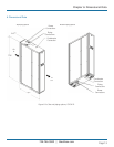
PIPING CONFIGURATION
Top piping: When top piping is specified, the Cold Row CW units must be provided with connections for both chilled water
piping and condensate discharge on the top of the cabinet.
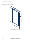
Bottom piping: When bottom piping is specified (for example, raised floor applications), the Cold Row CW units must be provided
with connections for both chilled water and condensate pump discharge through the bottom of the cabinet.
CONDENSATE PUMP
The Cold Row CW must include a factory-wired and installed, in-pan condensate pump. The condensate pump must have the
capacity of 40 gal/hr. at 6 ft. of lift with a maximum shutoff (head) of 12 ft. The condensate pump must be piped with either top
or bottom discharge connections, to remain consistent with top or bottom chilled water piping connections.
2-WAY (STANDARD)
A 2-way modulating valve rated for a maximum 400 psig w.w.p. must be factory piped and wired. The 2-way chilled water
modulating valve will automatically meter the flow of chilled water to the cooling coil in response to a proportional signal
(0–10 VDC) provided to the valve by the microprocessor controller w.w.p.
3-WAY (OPTIONAL)
The water circuit must include a factory-mounted, 3-way modulating (0–10 VDC) control valve. Design pressure must be
400 psig.
STEAM-GENERATING HUMIDIFIER FOR 24" CABINET DESIGN (CRCW-24)
The humidifier must be a self-contained, steam-generating electrode type, using a plastic disposable cylinder with full probes,
connected to electric power via cylinder plugs that slide onto the electrode pins. The electrode pins must be constructed from
expanded low carbon steel, zinc plated, and dynamically formed for precise current control. The humidifier assembly must include
an integral fill cup, fill and drain valves, and associated piping.
The canister must be designed to collect the mineral deposits in the water and provide clean, particle-free steam to the air stream,
reducing maintenance cost.
The microprocessor control must maintain humidifier operation through fill and drain cycles based on the water conductivity.
Overflow and loss of flow protection shall be provided along with a manual drain switch. A high water alarm with built-in time
delay shall provide an indication to change canister. The humidification system must not require cleaning maintenance during the
cylinder life.
The humidifier must discharge steam at 212 degrees F and atmospheric pressure. It must be capable of operating with water in
the range of 200 to 1500 micromhos. The steam must be introduced into the air stream, after the evaporator, by a calibrated
discharge tube designed to equally distribute the steam to the air stream without condensation. The humidifier must have a
capacity of 5 lb./hr.
A factory-wired and installed humidifier drain pump must be installed. This pump is designed to operate with the higher
condensate temperatures caused by the flush and drain cycle of the electrode canister humidifiers. The humidifier drain line will
be connected to the main condensate line prior to exiting the cabinet.
DEHUMIDIFICATION CYCLE
The Cold Row CW unit must have a dehumidification control mode. During dehumidification demand, the control mode must
permit chilled water valve operation and EC motor speed control to condense moisture on the cooling coil.