


Part No 811202 Form No F071408A
9
HTR/TR Owner’s Manual
ASSEMBLY
OPERATION
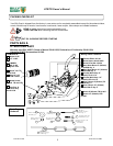
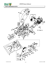
1. ASSEMBLE exhaust elbow (item 10), to main unit and firmly tighten knobs (item 90), that are preassembled to main unit.
2. SECURELY ATTACH unit to tailgate of a truck or to a trailer, so that the exhaust discharges into an enclosed container.
3. ATTACH hose to hose coupler (item 24), using hose clamp (item 60)
4. ASSEMBLE hose coupler to housing of main unit and securely tighten knob (item 13), that is preassembled to housing front plate.
5. ASSEMBLE nozzle handle loop (item 82), to nozzle handle using screw (item 80), washer (item 6) and lock nut (item 5). Adjust
handle loop to desired height and angle and securely tighten in place.
6. ASSEMBLE nozzle handle (item 78), to nozzle (item 77), using screws (item 80), washers (item 79), washers (item 4) and lock
nuts (item 5).
7. ATTACH assembled nozzle to hose using hose clamp (item 60). Before tightening hose clamp, position nozzle handle upward
when hose is stretched to prevent twisting load on hose assembly during operation.
8. ASSEMBLE tube square boom (item 51), to boom pivot (item 50), using chain loop assembly (item 54), washers (item 4) and lock
nut (item 52).
9. ASSEMBLE remaining chain loop assembly (item 54), to end of tube square boom (item 51) using washer (item 4) and lock nut
(item 52).
10. SLIDE boom assembly into square tube on front of housing.
11. ASSEMBLE hose bands (item 56) around hose and onto chain loop assemblies on boom assembly using screws (item 55) and
lock nuts (item 52) (see ADJUSTING HOSE BOOM on page 10).
Like all mechanical tools, reasonable care must be used when operating machine.
Inspect machine work area and machine before operating. Make sure that all operators of this
equipment are trained in general machine use and safety.
PUT OIL IN ENGINE BEFORE STARTING
STARTING
SECURE LOADER TO TAILGATE OR MOUNTING
ENGINE: See engine manufacturer’s instructions for type and amount of oil and gasoline used. Engine must be level when
checking and filling oil and gasoline.
ENGINE SPEED: Controlled by throttle lever on the frame (18HP Twin on engine). Under normal conditions, operate at
minimum throttle to accomplish your current cleaning task.
FUEL VALVE: Move fuel valve to "ON" position (when provided on engine).
INTAKE HOSE: Must be attached to front plate to start engine.
CHOKE: Located on engine near engine throttle panel.
STOP SWITCH: Move to on position (when provided).
THROTTLE: Move remote throttle control to fast position. Pull starting rope to start engine.
IF YOUR UNIT FAILS TO START:
See Troubleshooting on page 12.
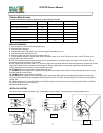
HANDLING & TRANSPORTING:
ALWAYS REMOVE LOADER FROM TAILGATE OR MOUNTING BEFORE TRANSPORTING OR OPENING
TAILGATE. Using two people to lift machine is recommended. Lift holding the rear handle and front of frame. Secure in place
during transport. See page 3 for weight specifications.
HOSE: DO NOT drag the hose with vehicle.
Never lift the machine while the engine is running.