


Part No 811202 Form No F071408A
11
HTR/TR Owner’s Manual
MAINTENANCE
P
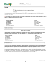
ERIODIC MAINTENANCE
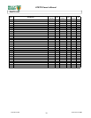
Periodic maintenance should be performed at the following intervals:
Maintenance Operation Every use Every 5 hours (daily) Every 25 Hours
Inspect for loose, worn or damaged parts.
z
Check engine oil and air filter
z
Clean hose
z
Engine (See Engine Manual)
Grease Exhaust Ring (see A pg. 14)
z
Keep engine free of debris
z
Check for excessive vibration
z
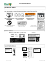
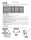
INTERLOCK SYSTEM
With hose coupler installed (as shown in Fig. 4) the switch is open & engine is not grounded out, allowing engine to run.
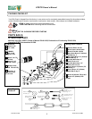
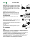
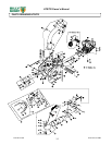
IMPELLER REMOVAL
1. Wait for engine to cool and disconnect spark plug.
2. Disconnect hose from unit.
3. Remove boom assembly.
4. Remove cable assy. interlock (item 43), from front plate of assembly (item 41).
5. Remove front plate assembly (item 41).
6. Remove impeller bolt (item 16) and lock washer (item 17).
7. Pull the impeller outward. If impeller slides freely, proceed to (steps 10 to 14 for TR units or to step 14 for HTR units). If not,
complete steps 8 thru 9 as required.
8. Place two crowbars between impeller and housing on opposite sides. Pry impeller away from engine until it loosens. Using a
p
enetrating oil can help loosen a stuck impeller.
9. If the impeller does not loosen, obtain a 1” (25.4mm) longer bolt of the same diameter and thread type as the impeller bolt. Thread
longer bolt by hand into the crankshaft until bolt bottoms. Using a suitable gear or wheel puller against the bolt head and the
impeller back-plate (near the blades), remove impeller from shaft.
10. [TR ONLY] Remove engine base mounting bolts, and nuts.
11. [TR ONLY] Access engine bolts on inside of housing that connect engine face to the fan housing. Bend ends of lock clip away
from bolt heads and remove bolts.
12. [TR ONLY] Slide engine shaft out of impeller.
13. [TR ONLY] When impeller is free of the engine shaft, align impeller with opening, and diagonally lift impeller out of housing.
14. Using a new impeller bolt and lockwasher (and engine bolt lock clip, TR only), reinstall (engine for TR only) and new impeller in
reverse order.
15. Tighten impeller bolt. Torque HTR1803V and TR1304H impeller bolt to [33-38 Ft. Lbs. (45-52 N.m)] and TR1204L to [55-60 Ft.
Lbs. (75-81 N.m)] (see item 16 on page 15).
16. Reinstall spark plug wire.
Fig. 3
Fig. 4
HTR1803V SYSTEM
TR1304H SYSTEM
TR1204L SYSTEM
ENGINE
SWITCH
INTERLOCK
SWITCH
Spark plug
IGNITION
UNIT
Spark plug
IGNITION
UNIT
ENGINE
SWITCH
INTERLOCK
SWITCH
Spark plug
IGNITION
UNIT
Throttle
stop