


21
ƽ
ƽ
ƽ
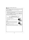
$IWHUWLJKWHQWKHVFUHZVOLJKWSXOOWKHZLUHDQGFRQILUPZKHWKHULVLWILUPRUQRW
ƽ
ƽ7KHFRYHUSODWHPXVWEHIL[HGDQGWLJKWHQWKHFRQQHFWLRQZLUHLILWLVSRRULQVWDOOHGWKDW
Install indoor unit
127(
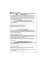
:KHQFRQQHFWLQJWKHHOHFWULFZLUHLIWKHZLUHOHQJWKLVQRWHQRXJKSOHDVHFRQWDFWZLWK
WKHDXWKRUL]HGVHUYLFHVKRSWREX\DH[FOXVLYHHOHFWULFZLUHWKDWLVORQJHQRXJKDQGWKH
MRLQWRQWKHZLUHDUHQRWDOORZHG
7KHHOHFWULFZLULQJPXVWEHFRUUHFWO\FRQQHFWHGZURQJFRQQHFWLRQPD\FDXVHVSDUHSDUWV
PDOIXQFWLRQ
7LJKWHQWKHWHUPLQDOVFUHZLQRUGHUWRSUHYHQWORRVH
,IWKHHDUWKZLUHLVZURQJFRQQHFWLRQWKDWPD\FDXVHHOHFWULFVKRFN
WKHGXVWPRLVWXUHPD\HQWHULQRUWKHFRQQHFWLRQWHUPLQDOZLOOEHDIIHFWHGE\RXWVLGHIRUFH
DQGZLOOFDXVHILUHRUHOHFWULFVKRFN
েৢ
ƽ
Ł
ł
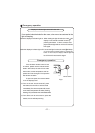
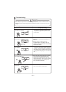
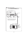
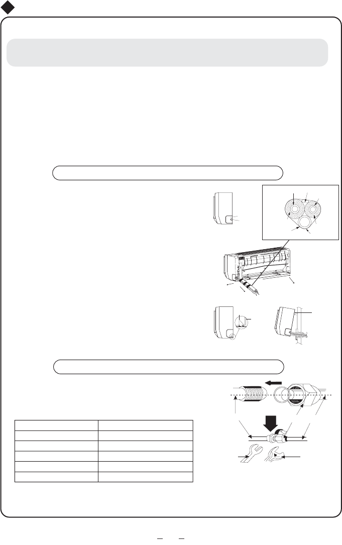
Install the indoor unit
The piping can be lead out from right, right rear, left
left rear.
When routing the piping and wiring from the left
or right side of indoor unit, cut off the tailings
from the chassis in necessary(Show in Fig.7)
Cut off the tailings 1 when routing the wiring only;
Cut off the tailings 1 and tailings 2 when routing
both the wiring and piping.
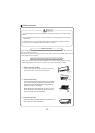
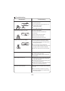
Take out the piping from body case, wrap the piping
electric wire, water pipe with tape and pull them
through the piping hole (As show in Fig.8)
Hange the mounting slots of the indoor unit on the
upper tabs of the rear panel and check if it is firm
enough.(As show in Fig.9)
The height of the installed location should be 2. m
or more from the floor.
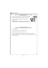
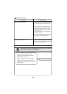
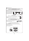
Install the connection pipe
Align the center of the piping flare with the relevant valve.
Screw in the flare nut by hand and then tighten the
nut with spanner and torque wrench refer to the
following:
NOTE: Firstly connect the connection pipe to indoor unit, then to outdoor unit; pay attention
to the piping bending, do not damage the connection
pipe; the joint nut couldn't tighten too
much, otherwise it may cause leakage.
Spanner
Torque
wrench
Piping
Taper nut
Indoor unit piping
Fig.9
Mounting
plate
Fixing hook
Mounting
baord
Right
Right rear
Fig.8
Left rear
Left
Fig.7
Tailing 1
Tailing 2
Finally wrap it
with tape
Gas side piping
insulation
Water drainage pipe
Liquid side
Piping insulation
Gas side pipe
External connection
electric wire
Liquid side piping
1gP
Ɏ
Ɏ
Ɏ
̚
̚
̚
Ɏ ̚
Ɏ ̚
Hex nut diameter
Tightening torque
5