


6104 BCF5 R06 Page 13
Set combustion using instruments
Allow the burner to run for approximately 5 to 10 min-
utes.
Set the stack or over-fi re draft to the level specifi ed by
the appliance manufacturer.
Natural Draft Applications; typically over-fi re draft
is -0.01” or -0.02” w.c.
Direct Venting; typically may not require draft adjust-
ment.
High Effi ciency/Positive Pressure Appliances; also
vary from traditional appliances (see manufacturer’s
recommendations).
Follow these four steps to properly adjust the burner:
Step 1: Adjust the air shutter/band until a trace of smoke
is achieved.
Step 2: At the trace of smoke level, measure the CO
2
(or O
2
) . This is the vital reference point for further
adjustments. Example: 13.5% CO
2
(2.6% O
2
)
Step 3: Increase the air to reduce the CO
2
by 1.5 to 2
percentage points. (O
2
will be increased by approxi-
mately 2.0 to 2.7 percentage points.) Example: Re-
duce CO
2
from 13.5% to 11.5% (2.6% to 5.3% O
2
).
Step 4: Recheck smoke level. It should be Zero.
This procedure provides a margin of reserve air
to accommodate variable conditions.
If the draft level has changed, recheck the
smoke and CO2 levels and readjust the burner,
if necessary
Once combustion is set, tighten all fasteners on air band,
air shutter and escutcheon plate.
Start and stop the burner several times to ensure satis-
factory operation. Test the primary control and all other
appliance safety controls to verify that they function ac-
cording to the manufacturer’s specifi cations.
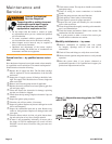
Check the breech draft pressure against the appliance
manufacturer’s recommended setting (typically + 0.1”
W.C.). If the breech pressure is higher or lower than rec-
ommended level, adjust the appliance breech damper to
achieve the specifi ed setting. Recheck the smoke and
CO
2
levels. Adjust burner air if necessary.
1.
2.
y
y
y
3.
y
y
4.
5.
6.
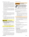
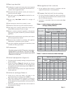
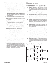
Figure 10. - Typical sequence of operation
Sequence of
operation — typical
Standby — The burner is idle, waiting for a call for
heat. When a call for heat is initiated, there is a 3- to
10-second delay while the control performs a safe start
check.
Valve-on delay — As applicable, the ignition and mo-
tor are turned on for a 15-second prepurge.
Trial for ignition (TFI) — The fuel valve is opened, as
applicable. A fl ame should be established within the 15-
second lockout time (30-second lockout time is avail-
able).
Lockout — If fl ame is not sensed by the end of the TFI,
the control shuts down on safety lockout and must be
manually reset. If the control locks out three times in a
row, the control enters restricted lockout. Call a quali-
fi ed service technician.
Ignition carryover — Once fl ame is established, the
ignition remains on for 10 seconds to ensure fl ame sta-
bility. It then turns off.
Run — The burner runs until the call for heat is satis-
fi ed. The burner is then sent to burner motor-off delay,
as applicable, or it is shut down and sent to standby.
Recycle — If the fl ame is lost while the burner is fi ring,
the control shuts down the burner, enters a 60-second
recycle delay, and then repeats the ignition steps out-
lined above. If the fl ame is lost three times in a row,
the control locks out to prevent continuous cycling with
repetitious fl ame loss caused by poor combustion.
Burner motor-off delay — If applicable, the fuel valve
is closed and the burner motor is kept on for the selected
postpurge time before the control returns the burner to
standby.
1.
2.
3.
4.
5.
6.
7.
8.
2
1
3
5
6
8
4
7
Standby
Motor-off
delay
(postpurge)
Valve-on
delay
Trial for
ignition
Ignition
carryover
Run
Lockout
Recycle