


Page 10 6104 BCF5 R06
Wire the burner — R7184
Disconnect electrical power before installing or servic-
ing the burner.
Provide ground wiring to the burner, metal control en-
closures and accessories. (This may also be required to
aid proper control system operation)
Perform all wiring in compliance with the National
Electric Code ANSI/NFPA 70 (Canada CSA C22.1).
y
y
y
Electrical shock can cause severe personal in-
jury or death.
Electrical Shock Hazard
Install the burner and all wiring in accordance with the National
Electrical Code and all applicable local codes or requirements.
Wire the burner in compliance with all instructions provided by
the appliance manufacturer. Verify operation of all controls in
accordance with the appliance manufacturer’s guidelines.
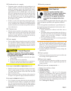
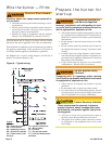
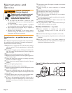
See Figure 9 for a typical wiring diagram, with R7184 oil
primary, for reference purposes only.
Keep Service Access
Covers Securely Installed
These covers must be securely in place to
prevent electrical shock, damage from exter-
nal elements, and protect against injury from
moving parts.
All covers or service access plates must be in place at
all times except during maintenance and service.
This applies to all controls, panels, enclosures, switch-
es, and guards or any component with a cover as part
of its design.
y
y
Safety controls are designed and installed to provide
protection.
Do not tamper with, or bypass any safety control.
If a safety control is not functioning properly, shut off
all main electrical power and fuel supply to the burner
and call a qualifi ed service agency immediately.
y
y
y
Tampering with, or bypassing safety controls
could lead to equipment malfunction and result
in asphyxiation, explosion or fi re.
Do Not Bypass Safety
Controls
Prepare the burner for
start-up
This burner must be installed and prepared for start-up
by a qualifi ed service technician who is trained and ex-
perienced in commercial oil burner system installation
and operation.
Do not attempt to start the burner unless you are fully
qualifi ed.
Do not continue with this procedure until all items in
the “Prepare the burner for start-up” section have been
verifi ed.
Carefully follow the wiring diagrams, control instruc-
tion sheets, fl ame safeguard sequence of operation, test
procedures and all appliance manufacturer’s directions
that pertain to this installation.
If any of these items are not clear or are unavailable,
call Beckett at 1-800-645-2876 for assistance.
y
y
y
y
y
Incorrect installation and mishandling of start-
up could lead to equipment malfunction and re-
sult in asphyxiation, explosion or fi re.
Professional Installation
and Service Required
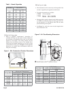
Figure 9. - Typical wiring
Legend
FD = Fused disconnect
LM = Limit controls
OP = Operating controls
PR = Oil primary controls
CC = Flame sensor, CAD
Cell type
TR = Ignition transformer
M1 = Burner Motor
S1 = Oil Valve
T-T = 24-volt thermostat
F-F = CAD cell fl ame sensor
terminals