


Beckett
Instruction Manual – Model AFII Oil Burne
r
Prepare burner & site
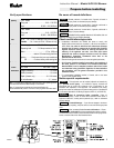
Prepare burner
• Use a wrench or vise to hold the nozzle adapter. DO NOT attempt to
remove or replace nozzle without holding adapter. The nozzle alignment
could be seriously damaged. Use a nozzle wrench that secures the
adapter or use
3
/
4
" and
5
/
8
" open-end wrenches.
Burner fuel unit
• Verify that the burner fuel unit is compatible with the oil supply system. For
more details, refer to “Connect fuel lines” on page 8.
• Do not squeeze the electrodes too tightly when handling the nozzle line
assembly. This could change the electrode tip settings or damage the
ceramic electrode insulators.
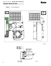
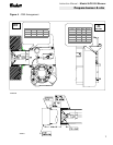
Attach air tube (if not already installed)
If using a flange and gasket, slide them onto the air tube. Then attach the air
tube to the burner chassis using the sheet metal screws provided. See Figures
3 & 4 on pages 6 & 7 for details.
• Carefully check and realign electrode tips after replacing nozzle,
ensuring the electrode settings comply with Figure 2a or 2b.
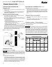
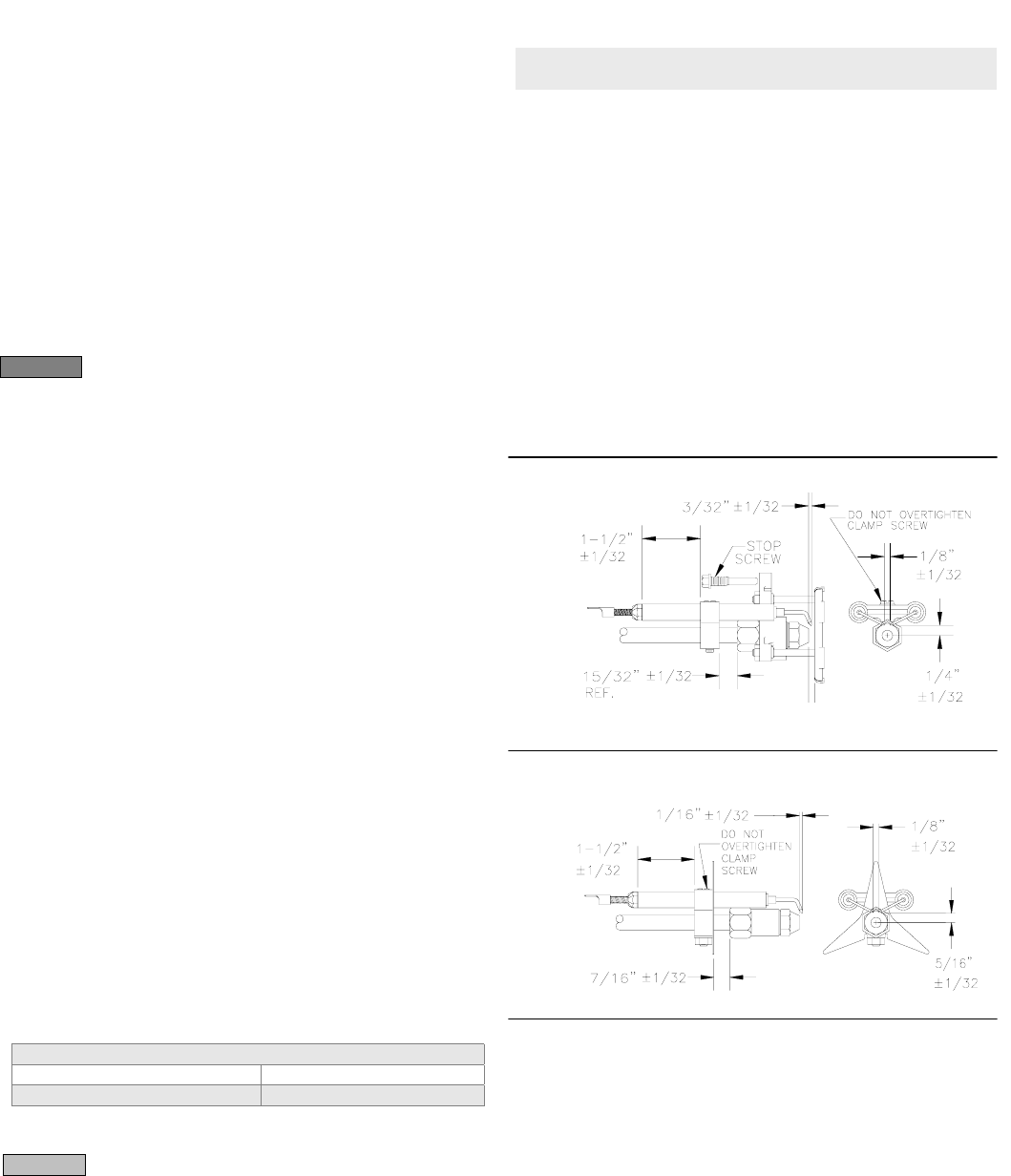
Check/adjust electrodes
Install burner nozzle (if not already installed)
Check the electrode tip settings. Adjust if necessary to comply with the
dimensions shown in Figure 2a or Figure 2b. To adjust, loosen the electrode
clamp screw and slide/rotate electrodes as necessary. Securely tighten the
clamp screw when finished.
Make certain the nozzle is selected for the fuel unit pressure
used. For applications with fuel unit pressure above 100 psig, the nozzle rated
capacity will be less than the appliance firing rate. Use only the specified spray
pattern unless combustion test results indicate the need for a change. Failure
to use the correct nozzle size and type can result in unacceptable combustion,
possibly causing severe personal injury, death or substantial property
damage.
WARNING
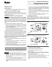
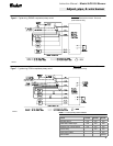
Figure 2a
– Electrode settings – HLX Air Tube Combinations
1. Remove the plastic plug protecting the nozzle adapter threads
2. Place a ¾” open-end wrench on the nozzle adapter. Insert the nozzle into
the adapter and finger tighten. Finish tightening with a
⅝”
open-end
wrench. Use care to avoid bending the burner head support legs or
electrodes. See
CAUTION
, below.
3. If you remove the head to replace the nozzle (type “HLX” heads), carefully
reconnect the head to the nozzle adapter, making sure to butt the head
support to the nozzle adapter shoulder (see Figure 3, page 6).
If the nozzle is already installed, remove the nozzle line assembly to verify that
the nozzle size and spray pattern are correct for the application (per appliance
manufacturer’s information or Beckett OEM Specification Guide, part number
6711). Verify that the electrode tip settings comply with Figure 2a or 2b.
If the nozzle is not installed, obtain a nozzle of the manufacturer, capacity and
spray angle specified in appliance manufacturer’s information or Beckett OEM
Specification Guide
, part number 6711. For conversions or upgrades, when
information is not available for the application:
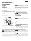
Figure 2b
– Electrode settings – FBX Air Tube Combinations
4. Refer to table below to select the mid-range nozzle spray angle for the
head type being used.
5. Fire the burner and make sure the combustion is acceptable and the
flame is not impinging on chamber surfaces.
6. If a shorter flame is needed, select a wider spray angle. If a longer flame
is needed, select a narrower spray angle.
7. Either hollow or solid spray patterns may be used. If combustion results
are not satisfactory with the selected spray pattern, try the other pattern.
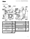
Servicing nozzle line assembly
Recommended nozzle spray angles
“HLX” heads
45°, 60°, or 70° nozzle
“FBX” heads
60°, 70°, or 80° nozzle
1. Turn off power to burner before proceeding.
2. Disconnect copper oil connector tube from nozzle line.
3. Loosen the screw that fastens the rear access door.
4. Remove splined nut.
5. Remove the nozzle line assembly from the burner, being careful not to
damage the electrodes or insulators while handling. Stop halfway to
remove igniter/transformer wires.
Use care when removing and installing oil nozzles:
SK8811
SK8263
• Inspect the nozzle adapter before installing nozzle. If it is grooved or
scratched on the sealing surface, replace the nozzle line assembly.
Otherwise, oil could leak at the nozzle-adapter joint, causing serious
combustion problems.
CAUTION
6. To replace the nozzle assembly, reverse the above steps.
“HLX” head air tubes – Be sure stop screw is fastened securely. Seat
stop screw on back of choke ring to set the position of the head.
•
Protect the nozzle orifice and strainer when installing. If the orifice gets
dirt in it or is scratched, the nozzle will not function properly.
“
FBX
” head air tubes – Use T gauge to set the “Z” dimension to 1-1/8” +/-
1/32”.
•
Do not over-torque the nozzle when installing. This will cause deep
grooves in the nozzle adapter, preventing a seal when a new nozzle is
installed.
5