


Instruction Manual – Model AFII Oil Burner
Beckett
Startup & adjust burner Service & maintain burner
Startup burner/set combustion Perform regular maintenance
Do not attempt to start the burner when excess fuel or vapor
has accumulated in the appliance. Starting the burner under these conditions
could result in a puffback of hot combustion gases, high smoke levels, or
otherwise hazardous operation.
WARNING
This equipment must be serviced only by a qualified service
agency. The appropriate test instruments must be used. Failure to do so could
result in burner or appliance failure, causing potential severe personal injury,
death or substantial property damage.
WARNING
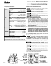
1. Open the shutoff valves in the oil supply line to the burner.
Replace the oil supply line filter. The line filter cartridge must be replaced
to avoid contamination of the fuel unit and nozzle.
2. Open the air dial. This is an initial air setting for the pump bleeding
procedure only. Additional adjustments must be made with instruments.
Inspect the oil supply system. All fittings should be leak-tight. The supply
lines should be free of water, sludge and other restrictions.
3. Set the thermostat substantially above room temperature.
4. Close the line voltage switch to start the burner. If the burner does not
start immediately you may have to reset the safety switch of the burner
primary control.
Remove and clean the pump strainer if applicable.
Replace the nozzle with an equivalent nozzle.
Clean and inspect the electrodes for damage, replacing any that are
cracked or chipped.
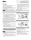
5. Bleed air from the fuel unit as soon as burner motor starts rotating.
Check electrode tip settings. Replace electrodes if tips are rounded.
To bleed the fuel unit, attach a clear plastic hose over the vent fitting.
Loosen the fitting and catch the oil in an empty container. Tighten the
fitting when all air has been purged from the oil supply system.
Inspect the igniter cables and connections.
Clean the cad cell grid surface, if necessary.
Make sure the burner housing baffle is in place if required for the burner
application (AFII 85 & AFII 100). Omitting the baffle can result in
unacceptable burner combustion.
•
If the burner locks out on safety during bleeding, reset the safety
switch and complete the bleeding procedure. Note — Electronic
safety switches can be reset immediately; others may require a three-
to five-minute wait.
Inspect all gaskets. Replace any that are damaged or would fail to seal
adequately.
• If burner stops after flame is established, additional bleeding is
probably required. Repeat the bleeding procedure until the pump is
primed and a flame is established when the vent fitting is closed.
Clean the blower wheel, air inlet, air guide, and retention head of any lint
or foreign material.
If motor is not permanently lubricated, oil motor with a few drops of SAE
20 nondetergent oil at each oil hole. DO NOT over oil motor. Excessive
oiling can cause motor failure.
• For R7184 primary controls, see Technician’s Quick Reference Guide,
part number 61351 or 61465, for special pump priming sequence.
• Prepare for combustion tests by drilling a ¼" sampling hole in the flue
pipe between the appliance and the barometric draft regulator.
Check motor current. The amp draw should not exceed the nameplate
rating by more than 10%.
6.
Initial air adjustment
— Using a smoke tester, adjust the air dial (and
change firing pin on HLX ATC’s, if necessary) to obtain a clean flame.
Now the additional combustion tests with instruments can be made.
Check all wiring for secure connections or insulation breaks.
Check the pump pressure and cutoff function.
Check primary control safety lockout timing.
Set combustion with instruments
Check ignition system for proper operation.
Inspect the vent system and chimney for soot accumulation or other
restriction.
The combustion must be adjusted using test instruments.
Failure to do so could result in burner or appliance failure, causing potential
severe personal injury, death or substantial property damage.
WARNING
Clean the appliance thoroughly according to the manufacturer's
recommendations.
1. Let burner run for approximately 5 to 10 minutes.
Check the burner performance. Refer to the section “Set combustion
with instruments
”.
2. Set the over-fire or stack draft to level specified by appliance manufacturer
(usually –0.01 to –0.02 inches w.c. over-fire for natural draft applications).
It is good practice to make a record of the service performed and the
combustion test results.
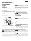
3. Follow these four steps to properly adjust the burner:
Step 1:
Adjust air until a trace smoke level is achieved
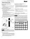
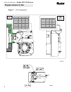
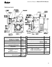
To replace the blower wheel:
Step 2:
At the trace of smoke level, measure the CO
2
(or O
2
). This is
the vital reference point for further adjustments.
1. Turn off all power to the burner before servicing.
•
Example: 13.5% CO
2
(2.6% O
2
)
2. Disconnect the burner motor wires.
3. Remove the bolts securing the blower motor to
the housing.
Step 3:
Increase the air to reduce CO
2
by 1 to 2 percentage points. (O
2
will be increased by approximately 1.4 to 2.7 percentage points.)
4. Remove the blower motor and wheel.
•
Example: Reduce CO
2
from 13.5% to 11.5%. (O
2
– 2.6% to 5.3%)
5. Remove the existing wheel.
Step 4:
Recheck smoke level. It should be zero.
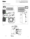
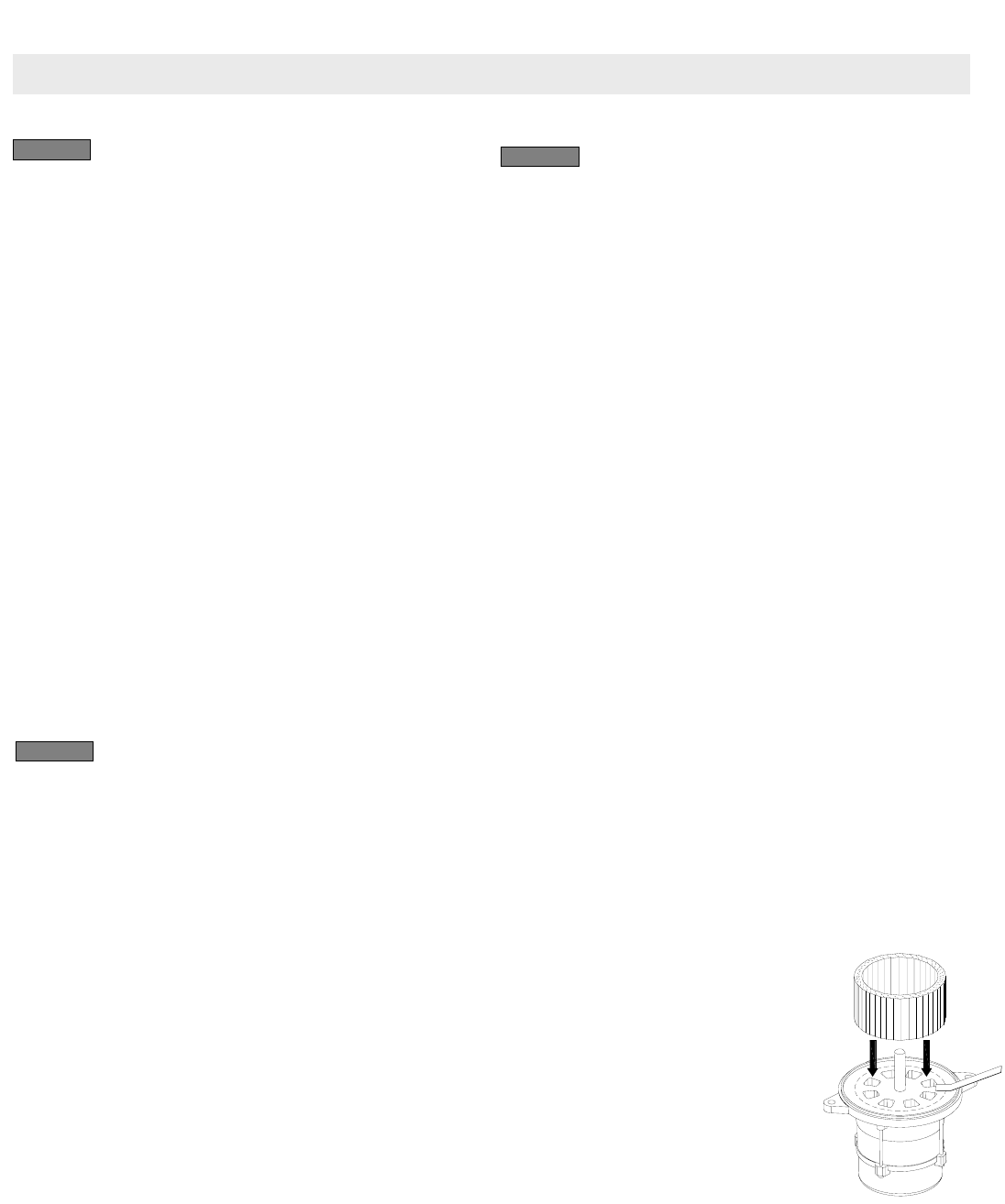
6. As shown at right, slide the new blower wheel
onto the shaft.
•
This procedure provides a margin of reserve air to accommodate
variable conditions.
• Place a .062" (1/16" ± 1/64") feeler gauge on
the motor as shown.
• If the draft level has to be changed, recheck the smoke and CO
2
levels. Adjust the burner air if necessary.
•
Slide blower wheel toward motor until it
contacts feeler gauge.
4. Once combustion is set, tighten all fasteners on air dial, rear access door
and escutcheon plate.
•
Rotate the wheel until the setscrew is
centered on the flat of the motor shaft.
Tighten the setscrew to secure the wheel.
5. Start and stop the burner several times to ensure satisfactory operation.
Test the primary control and all other appliance safety controls to verify
that they function according to the manufacturer’s specifications.
SK9190A
7. DO NOT use any motor other than the original equipment type motor.
8.
Install the motor on the burner housing. Tighten screws. Reconnect wires.
9. Restore power, start the burner and perform combustion tests. Refer to
the section “
Set combustion with instruments
”.
10