


RWB 6104 BAFII R01 Page 11
If motor is not permanently lubricated, oil motor
with a few drops of SAE 20 nondetergent oil at
each oil hole. DO NOT over oil motor. Exces-
sive oiling can cause motor failure.
Check motor current. The amp draw should
not exceed the nameplate rating by more than
10%.
Check all wiring for secure connections or in-
sulation breaks.
Check the pump pressure and cutoff function.
Check primary control safety lockout timing.
Check ignition system for proper operation.
Inspect the vent system and chimney for soot
accumulation or other restriction.
Clean the appliance thoroughly according to
the manufacturer’s recommendations.
Check the burner performance. Refer to the
section “Set combustion with test instruments”.
It is good practice to make a record of the ser-
vice performed and the combustion test re-
sults.
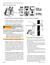
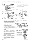
Removing Nozzle Line for Service
•
Remove the nozzle line assembly from the burn-
er, being careful not to damage the electrodes or
insulators while handling. Stop halfway to remove
igniter/transformer wires.
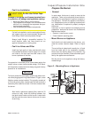
To replace the nozzle assembly, reverse the
above steps. “HLX” head air tubes – Be sure stop
screw is fastened securely. Seat stop screw on
back of choke ring to set the position of the head.
“FBX” head air tubes – Use T gauge to set the “Z”
dimension to 1-1/8” +/- 1/32”
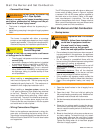
Nozzle Installation
Perform the following steps when replacing a noz-
zle.
Remove the nozzle line assembly to gain access
to the nozzle.
Use a 3/4” open-end wrench to hold the nozzle
adapter. DO NOT attempt to remove or replace
the nozzle without securing the adapter, as noz-
zle alignment could be seriously affected.
Do not squeeze the electrodes when handling
the nozzle line assembly. Excessive force could
change the electrode tip settings or damage the
ceramic electrode insulators.
Use a 5/8” open-end wrench to carefully remove
the existing nozzle.
5.
6.
•
1.
2.
3.
4.
Turn off power to burner before proceeding.
Disconnect copper oil connector tube from noz-
zle line.
Loosen the screw that fastens the rear access
door.
Remove splined nut.
1.
2.
3.
4.
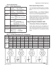
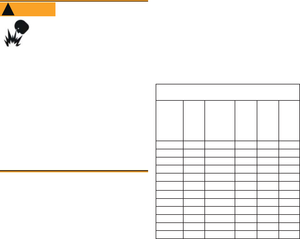
Use only nozzles having the brand, fl ow rate (gph), spray
angle and pattern specifi ed by the appliance manufactur-
er or Beckett Residential Burner OEM Spec Guide, Part
#6711.
Follow the appliance manufacturer’s specifi cations for the
required pump outlet pressure for the nozzle, since this
affects the fl ow rate.
Nozzle manufacturers calibrate nozzle fl ow rates
at 100 psig.
This burner utilizes pressures higher than 100
psig, so the actual nozzle fl ow rate will be greater
than the gph stamped on the nozzle body. (Exam-
ple: A 1.00 gph nozzle @ 140 psig = 1.18 gph)
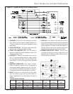
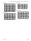
For typical nozzle fl ow rates at various pressures see ac-
companying chart.
•
•
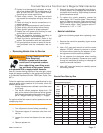
Incorrect nozzles and fl ow rates
could result in impaired combus-
tion, under-fi ring, over-fi ring, soot-
ing, puff-back of hot gases, smoke
WARNING
!
Correct Nozzle and Flow
Rate Required
and potential fi re or asphyxiation hazards.
Trained Service Technician’s Regular Maintenance
Nozzle fl ow rate U. S. gallons per hour of No. 2 fuel oil when
pump pressure (psig) is:
Nozzle
size
(rated
at 100
psig)
125
psi
140 psi
(factory
std.)
150
psi
175
psi
200
psi
0.40 0.45 0.47 0.49 0.53 0.56
0.50 0.56 0.59 0.61 0.66 0.71
0.60 0.67 0.71 0.74 0.79 0.85
0.65 0.73 0.77 0.80 0.86 0.92
0.75 0.84 0.89 0.92 0.99 1.06
0.85 0.95 1.01 1.04 1.13 1.20
0.90 1.01 1.07 1.10 1.19 1.27
1.00 1.12 1.18 1.23 1.32 1.41
1.10 1.23 1.30 1.35 1.46 1.56
1.20 1.34 1.42 1.47 1.59 1.70
1.25 1.39 1.48 1.53 - -
1.35 1.51 - - - -
Nozzle Flow Rate by Size