


Page 10 RWB 6104 BAFII R01
If the burner locks out on safety during bleed-
ing, reset the safety switch and complete the
bleeding procedure. Note — Electronic safety
switches can be reset immediately; others may
require a three- to fi ve-minute wait.
If burner stops after fl ame is established, addi-
tional bleeding is probably required. Repeat the
bleeding procedure until the pump is primed
and a fl ame is established when the vent fi tting
is closed.
For R7184 primary controls, see Technician’s
Quick Reference Guide, part number 61351 or
61465, for special pump priming sequence.
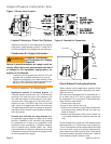
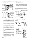
Prepare for combustion tests by drilling a 1/4”
sampling hole in the fl ue pipe between the ap-
pliance and the barometric draft regulator.
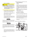
Initial air adjustment — Using a smoke tester,
adjust the air dial (and change fi ring pin on HLX
ATC’s, if necessary) to obtain a clean fl ame. Now
the additional combustion tests with instruments
can be made.
Set combustion with instruments
Allow the burner to run for approximately 5 to 10
minutes.
Set the stack or over-fi re draft to the level speci-
fi ed by the appliance manufacturer.
Natural Draft Applications; typically over-fi re
draft is -0.01” or -0.02” w.c.
Direct Venting; typically may not require draft
adjustment.
High Effi ciency/Positive Pressure Applianc-
es; also vary from traditional appliances (see
manufacturer’s recommendations).
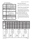
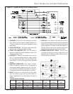
Follow these four steps to properly adjust the
burner:
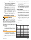
Step 1: Adjust the air dial until a trace of smoke is
achieved.
Step 2: At the trace of smoke level, measure the
CO
2
(or O
2
) . This is the vital reference point for
further adjustments. Example: 13.5% CO
2
(2.6%
O
2
)
Step 3: Increase the air to reduce the CO
2
by 1.5
to 2 percentage points. (O
2
will be increased by
approximately 2.0 to 2.7 percentage points.) Ex-
ample: Reduce CO
2
from 13.5% to 11.5% (2.6%
to 5.3% O
2
).
Step 4: Recheck smoke level. It should be Zero.
This procedure provides a margin of
reserve air to accommodate variable
conditions.
If the draft level has changed, recheck the
smoke and CO
2
levels and readjust the burner
if necessary
•
•
•
•
6.
•
1.
2.
•
•
•
3.
•
•
Once combustion is set, tighten all fasteners on
air dial, rear access door, and escutcheon plate.
Start and stop the burner several times to ensure
satisfactory operation. Test the primary control
and all other appliance safety controls to verify
that they function according to the manufactur-
er’s specifi cations.
Trained Service Technician’s Regular
Maintenance
4.
5.
Do not tamper with the burner or controls or
make any adjustments unless you are a trained
and qualifi ed service technician.
To ensure continued reliable operation, a quali-
fi ed service technician must service this burner
annually.
More frequent service intervals may be required
in dusty or adverse environments.
Operation and adjustment of the burner requires
technical training and skillful use of combustion
test instruments and other test equipment.
•
•
•
•
Tampering with or making incorrect
adjustments could lead to equip-
ment malfunction and result in
asphyxiation, explosion or fi re.
WARNING
!
Annual Professional Ser-
vice Required
The following guidelines are provided for routine
maintenance.
Replace the oil supply line fi lter. The line fi lter
cartridge must be replaced to avoid contamina-
tion of the fuel unit and nozzle.
Inspect the oil supply system. All fi ttings should
be leak-tight. The supply lines should be free of
water, sludge and other restrictions.
Remove and clean the pump strainer if appli-
cable.
Replace the nozzle with an exact replacement
as specifi ed by the appliance manufacturer.
Clean and inspect the electrodes for damage,
replacing any that are cracked or chipped.
Check electrode tip settings. Replace elec-
trodes if tips are rounded.
Inspect the igniter cables and connections.
Clean the cad cell grid surface, if necessary.
Inspect all gaskets. Replace any that are dam-
aged or would fail to seal adequately.
Inspect the combustion head and air tube. Re-
move any carbon or foreign matter. Replace all
damaged units with exact parts.
Clean the blower wheel, air inlet, air guide,
burner housing and nozzle line assembly of
any lint or foreign material.
Trained Service Technician’s Regular Maintenance