


7
GeniSys Control 24V Control Installation and Operation Manual
Priming the Pump■
To reset, interrupt power for at least 2
seconds.
Always verify the control functions
according to all specifi cations before
leaving the installation site.
Replace the control if it does not
operate as specifi ed.
1.
2.
3.
Prepare the burner for priming by
attaching a clear plastic hose over
the bleed port fi tting and fully opening
the pump bleed port. Use a suitable
container to collect purged oil.
Initiate a call for heat.
Bleed the pump until all froth and bubbles
are purged. If desired, terminate the call
for heat to return to Standby.
If prime is not established during the
valve on delay and the trial for ignition
times, repeat Step 3 until the pump is
fully primed and the oil is free of bubbles.
Terminate the call for heat, and the
control will resume normal operation.
Resetting From Lockout
1.
2.
3.
4.
5.
■
Do not allow oil to spray into a hot
combustion chamber while bleeding air
from the pump.
Install a gauge in the nozzle discharge
port tubing or fully open the pump
bleed valve to prevent oil spray from
accumulating in the combustion
chamber during the air bleed procedure.
Insure that all bubbles and froth are
purged from the oil supply system
before tightening the pump bleed valve.
Insure that the equipment is free of oil
and oil vapor before starting or resetting
the burner.
y
y
y
y
Failure to bleed the pump properly could
result in unstable combustion, hot gas
puff-back and heavy smoke.
Hot Gas Puff-Back &
Heavy Smoke Hazard
WARNING
Before starting or resetting
the control from lockout state,
troubleshoot the heating
system for the root cause(s) of
the lockout.
Fire & Smoke
Hazard
Make necessary repairs or adjustment
to ensure a safe start condition.
Insure that the equipment is free of
oil and oil vapors before starting or
resetting the burner.
y
y
WARNING
Maintenance
Oil heating systems require annual service
performed by a qualifi ed, professional
service agency. The 7559 primary control
should be inspected during this service
routine according to the following checklist:
The 7559 control has no
serviceable internal parts.
NOTICE
Inspect the exterior of the control.
Replace the control if there is any sign
of impact damage.
Use a multimeter to test the input
voltage at the control. It should read
21.6 to 30 Vdc.
Inspect all external wiring for secure
connections and verify insulation
integrity.
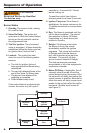
Verify the control lockout and operation
sequence, (Reference Startup/
Checkout section).
Observe a full operating cycle to prove
the sequence and timings are correct.
Replace any control that does not
meet listed specifi cations. Always
replace with the parts specifi ed by the
equipment manufacturer.
Replace a blown fuse with an
equivalent fast-acting automotive
blade style fuse (refer to Figure 1 for
fuse ratings and locations).
□
□
□
□
□
□
□