


Oil-Fired BCS Page 13
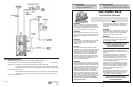
BOCK OIL-FIRED WATER HEATER
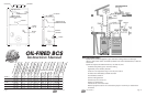
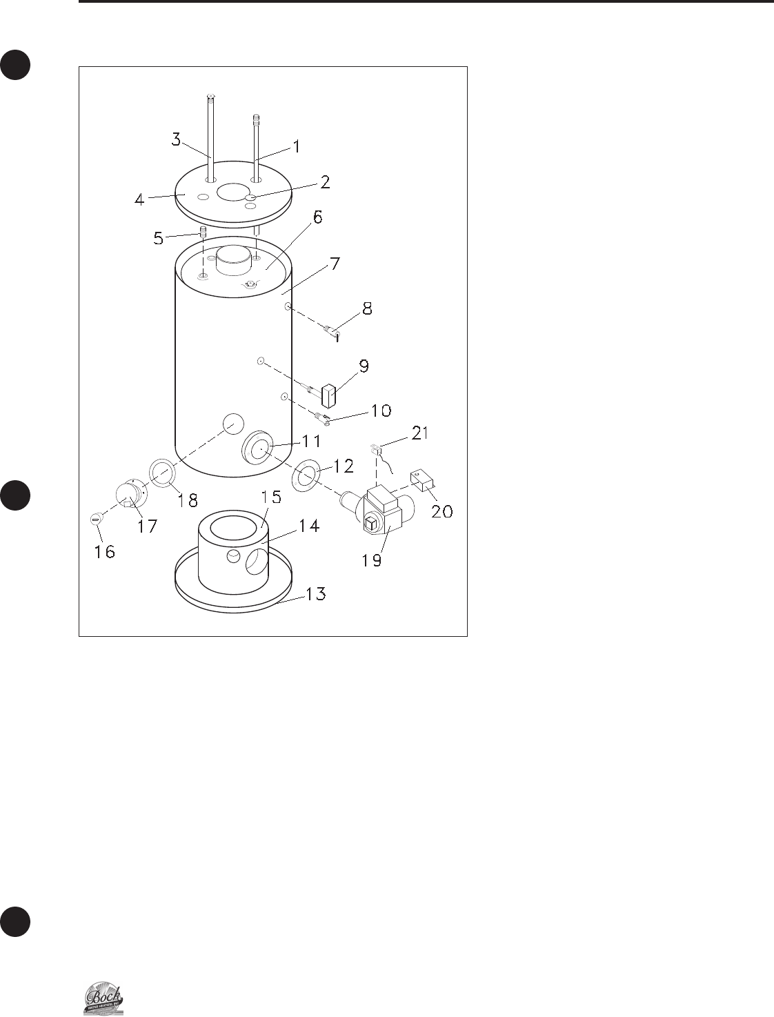
Bock Tank Assembly Parts List
W
hen ordering repair parts, always give
the part name, model number, size and
serial number.
I
TEM DESCRIPTION
1. Cold Water Inlet Dip Tube
2. Plastic Cap
3. Magnesium Rod
4. Top Pan
5. Hot Out Nipple
3
⁄4"
6. Tank
7. Heater Jacket
8. Temperature & Pressure Relief Valve
9. Immersion Well & Aquastat
10. Drain Valve
11. Burner Mounting Bracket
(part of jacket
assembly—32, 40, 51, BCS)
12. Mounting Bracket Gasket
13. Bottom Pan
14. Combustion Chamber Sleeve
15. Combustion Chamber
16. Sight Glass
17. Inspection Door
18. Not Used
19. Burner
20. Primary Relay
21. Cad Cell
Page 4 Oil-Fired BCS
1. Cut a 7" O.D. opening in the preferred wall and provide a minimum of
1
⁄2" clearance
of non-combustible space around the Balanced Flue. The opening should allow for a
1
⁄2"
downward pitch to the outside for drainage of any condensate in the Balanced Flue.
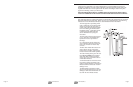
2. Insert the Balanced Flue from the
i
nside through the wall. Check the
outside extension to be sure air inlet
h
oles are exposed and will not be
covered by the flashing ring. Fasten
the assembly to the inside wall with
the tabs provided (see installation
detail drawing). On the outside
wall, install the flashing ring pro-
vided. Caulk around the outer and
inner rim of the flashing ring to
prevent moisture from entering
through the wall.
2 Mounting Tabs:
Attach to vent with
4 metal screws
supplied.
A
ttach vent to
b
uilding structure
w
ith 4 appropriate screws.
(
customer supplied)
Installation Detail
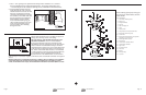
WATER HEATER PLACEMENT
NOTE: Locate the heater so it is not subject to physical
damage from moving vehicles or flooding.
DO NOT INSTALL THE WATER HEATER ON COM-
BUSTIBLE FLOORING. Place on noncombustible
flooring and maintain clearances prescribed by this
manufacturer and per code NFPA 31. If the water heater
must be located on combustible flooring it should be
raised off the floor with a layer of 4" concrete block laid
so the air holes are aligned as shown in the drawing at
left. Please contact Bock Water Heaters or consult NFPA
31 with questions concerning proper flooring materials.
Leave adequate room for periodic maintenance of
heater and burner. The heater should be placed as near to the Balanced Flue as convenient in
order to keep vent connector length to a minimum, with a maximum horizontal run length of
15 feet.
Minimum clearance to combustible construction is: SIDES 6"; BACK 6"; FRONT 24". The installation
of this water heater must conform with local codes and ordinances. In the absence of local
codes, the installation must comply with the National Fir
e Pr
otection Association (NFP
A 31) Code.