


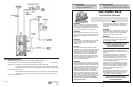


Oil-Fired BCS Page 5
CONNECT WATER PIPING
Be careful not to apply any heat to the water heater nipples. Install dielectric unions and shut
o
ff valves on both hot and cold water lines.
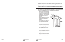
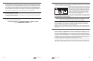
40 BCS models are equipped with a brass inlet bushing in-
stalled in the tank. Heaters equipped with this bushing are
marked next to the inlet by the decal shown on the left.
T
he purpose of this bushing is to help keep the tank bot-
tom free of sediment by aiding tank flushing. This bush-
ing must be located as shown on the decal to function
properly. Do not allow the bushing to rotate out of posi-
tion when tightening the inlet fittings.
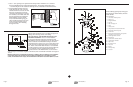
An approved pressure and temperature relief valve is factory installed in the opening provided
in the upper right-hand side of the water heater. Pipe the T&P to within 6" of the floor or to a
floor drain with a free flowing drain pipe.
CAUTION: Scalding injury and/or water damage can occur from either the manual
lifting of the lever or the normal operation of the T&P valve if it is not piped to a proper
drain. If the valve fails to flow water or reseat, call your plumber.
Check incoming water line for backflow preventers or water pressure reducing valves, as these
may cause pressure to build up in the water heater and result in tank failure. If this water
heater is installed in a closed system or if backflow preventers and pressure regulators are
installed, a properly sized expansion tank must be installed.
Note: Do not try to heat hard water as this will drastically reduce heater life. Install a water
softener if the water heater is being installed in a hard water area (water hardness higher than
seven grains).
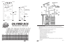
EXHAUST VENT
Where clearances to combustibles are a concern use double wall venting. Venting ap-
proved for Category III applicances is ideal but not required, single wall venting may be used
if allowed by local code. Caution: Do not use B-vent. The vent connector from the heater to
the rear of the Balanced Flue should be made using galvanized or stainless (preferred) vent ma-
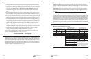
terial with a 4'' minimum diameter. A 6" × 4" reducer is placed on top of the heater flue. Note:
For 190E-BCS, a 6" vent pipe is preferred. Use one elbow to connect the heater to the venting.
An additional elbow may be used if the maximum horizontal distance from the BCS outlet to
the heater is reduced three feet. Maximum horizontal distance is 15 feet.
Venting from the heater to the Balanced Flue should be sealed but does not have to be pressure
tight. High temperature stainless sealing tape (2" wide) or high temperature (+500°F) RTV sili-
con sealants are recommended. Make certain the flue connector is removable for servicing.
OUR TOTAL WARRANTY COMMITMENT
We will not assume, nor authorize any person to assume for us, any other liability in connec-
tion with the sale or operation of Bock Water Heaters. Any implied warranties, including mer-
chantability or fitness for a particular application, imposed on the sale of this heater under
laws of the state of sale are limited to one year. Some states do not allow limitations on how
l
ong an implied warranty lasts, or for the exclusion of incidental or consequential damages, so
the above limitations or exclusions may not apply to you. This warranty gives you specific
l
egal rights, and you may also have other rights which vary from state to state.
WARRANTY REGISTRATION CARD
The attached warranty registration card should be returned within 30 (thirty) days of the date
of installation, otherwise the date of manufacture will be recorded as the date of installation
for the purpose of this warranty.
TO MAKE A CLAIM
Contact your nearest Bock distributor or:
Bock Water Heaters, Inc. • 110 South Dickinson Street • Madison, WI 53703
Telephone 608-257-2225 • Fax 608-257-5304
www.bockwaterheaters.com
Page 12 Oil-Fired BCS