


Manual 2100-426
Page 15
TROUBLESHOOTING
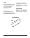
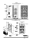
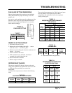
FIGURE 10
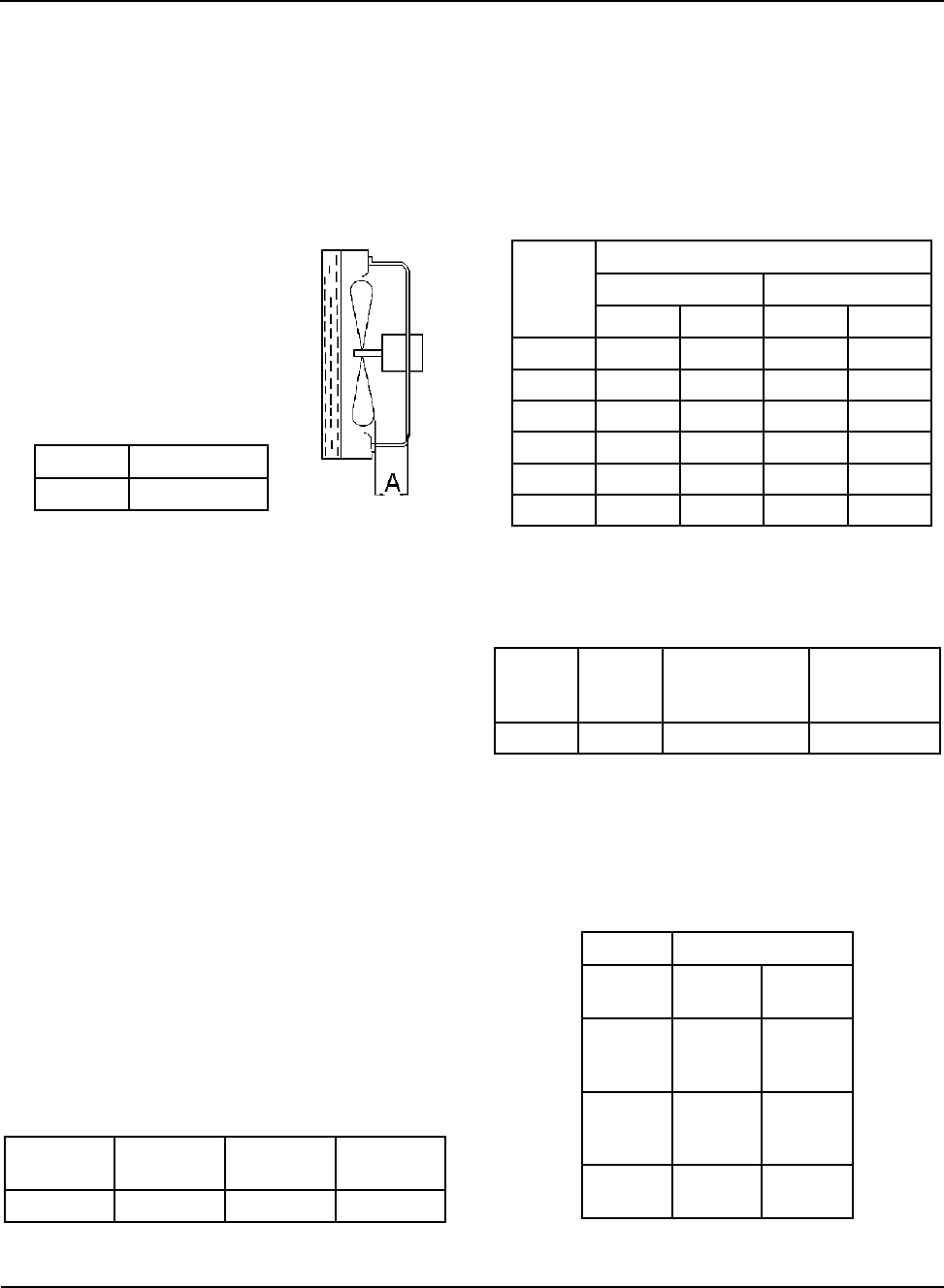
FAN BLADE SETTING
FAN BLADE SETTING DIMENSIONS
Shown in the drawing below are the correct fan blade
setting dimensions for proper air delivery across the
outdoor coil.
Any service work requiring removal or adjustment in the
fan and/or motor area will require that the dimensions
below be checked and blade adjusted in or out on the
motor shaft accordingly.
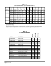
The suction line temperatures in Table 8 are based upon
80ºF dry bulb/67ºF wet bulb (50 percent R.H.)
temperature and rated airflow across the evaporator
during cooling cycle.
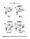
REMOVAL OF FAN SHROUD
1. Disconnect all power to unit.
2. Remove the screws holding both grills – one on
each side of unit – and remove grills.
3. Remove screws holding fan shroud to condenser and
bottom – (9) screws.
4. Unwire condenser fan motor.
5. Slide complete motor, fan blade, and shroud
assembly out the left side of the unit.
6. Service motor/fan as needed.
7. Reverse steps to reinstall.
REFRIGERANT CHARGE
The correct system R-22 charge is shown on the unit
rating plate. Optimum unit performance will occur with
a refrigerant charge resulting in a suction line
temperature
(6 inches from compressor) as shown in the following
table:
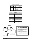
TABLE 7
FAN BLADE DIMENSIONS
ledoMAnoisnemiD
07LW
52.1
TABLE 8
SUCTION LINE TEMPERATURES
11
1
11
sledoM
detaR
wolfriA
F°59
.pmeTDO
F°28
.pmeTDO
07LW
008,106-8585-65
TABLE 9
INDOOR BLOWER PERFORMANCE
CFM AT 230 V
.P.S.E
HnI
2
O
07LW
deepShgiHdeepSwoL
lioCyrDlioCteWlioCyrDlioCteW
0.002,2000,2006,1054,1
1.001,2009,1525,1573,1
2.000,2008,1------
3.578,1007,1------
4.577,1006,1------
5.056,1574,1------
TABLE 11
MAXIMUM ESP OF OPERATION
ELECTRIC HEAT ONLY
ledoM07LW
deepS
WK
woL
deepS
hgiH
deepS
00A-
50A-
01A-
05.
05.
05.
05.
05.
00B-
90B-
51B-
05.
05.
05.
05.
05.
05.
90C-
51C-
05.
05.
05.
05.
j
TABLE 10
CFM AND ESP
detaR
ledoM
detaR
MFC
dednemmoceR
PSE
wolFriA
egnaR
07LW008,102.573,1--000,2
Rated CFM and ESP on high speed tap.