


Contents
Figures
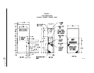
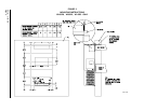
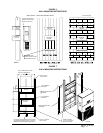
Figure 1 Unit Dimensions ..................................... 3
WA602N, WA6023, WA4823
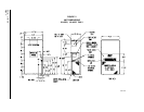
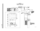
Figure 2 Unit Dimensions ..................................... 4
WA6022, WA4822
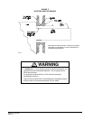
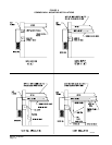
Figure 3 Mounting Instructions ............................. 8
WA602N, WA6023, WA4823
Figure 4 Mounting Instructions ............................. 9
WA6022, WA4822
Figure 5 Electric Heat Clearance ....................... 10
Figure 6 Wall Mounting Instructions ................... 11
Figure 7 Wall Mounting Instructions ................... 11
Figure 8 Common Wall Mounting Installations ... 12
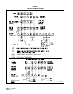
Figure 9 Unit 24V Terminal Board ...................... 14
Figure 10 Fan Blade Setting................................. 17
T
ables
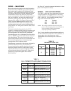
Table 1 Electric Heat Table ................................. 2
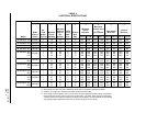
Table 2 Electrical Specifications ......................... 5
Table 3 Thermostat Wire Size ..........................13
Table 4 Wall Thermostat and Subbase
Combinations .......................................13
Table 5 Fan Blade Dimensions .........................17
Table 6 Indoor Blower Performance .................17
Table 7 Refrigerant Charge............................... 17
Table 8 Rated CFM and Rated ESP .................17
Table 9 Maximum ESP of Operation
Electric Heat Only ................................ 18
Table 10 Pressure Table ..................................... 18
Table 11 Optional Accessories ...........................19
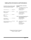
Getting Other Information and Publications 1
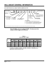
Wall Mount General Information
Air Conditioning Wall Mount Model Nomenclature . 2
Shipping Damage ...................................................6
General ...............................................................6
Duct Work............................................................... 6
Condensate Drain................................................... 6
Filters ............................................................... 6
Installation Instructions
Wall Mounting Information...................................... 7
Mounting the Unit ................................................... 7
Wiring – Main Power ............................................13
Wiring – Low Voltage Wiring ................................13
Start Up
Important Installer Note ........................................ 15
Crankcase Heaters ............................................... 15
High Pressure Switch ........................................... 15
Three Phase Scroll Compressor Start Up ............ 15
Service Hints ........................................................ 15
Sequence of Operation......................................... 15
Compressor Control Module................................. 15
Adjustments .......................................................... 16
Phase Monitor ...................................................... 16
Pressure Service Ports......................................... 16
Troubleshooting
Fan Blade Setting Dimensions ............................. 17
Removal of Fan Shroud........................................ 17
Refrigerant Charge ...............................................17
Pressure Table...................................................... 18
Optional Accessories ............................................19