


Manual 2100-193O
Page 20 of 26
IMPORTANT INSTALLER NOTE
For improved start-up performance, wash the indoor
coil with a dishwashing detergent.
CRANKCASE HEATERS
All units are provided with some form of compressor
crankcase heat.
All single and three phase models have an insertion
well-type heater located in the lower section of the
compressor housing. This is a self-regulating type
heater that draws only enough power to maintain the
compressor at a safe temperature.
Some form of crankcase heat is essential to prevent
liquid refrigerant from migrating to the compressor,
causing oil pump out on compressor start up and
possible valve failure due to compressing a liquid.
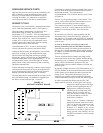
The decal in Figure 15 is affixed to all outdoor units
detailing start up procedure. This is very important.
Please read carefully.
SERVICE HINTS
1. Caution owner/operator to maintain clean air filters at
all times. Also, not to needlessly close off supply
and return air registers. This reduces airflow through
the system, which shortens equipment service life as
well as increasing operating costs.
2. Switching to heating cycle at 75°F or higher outside
temperature may cause a nuisance trip of the remote
reset high pressure switch. Turn thermostat off then
on to reset the high pressure switch.
3. The heat pump wall thermostats perform multiple
functions. Be sure that all function switches are
correctly set for the desired operating mode before
trying to diagnose any reported service problems.
4. Check all power fuses or circuit breakers to be sure
they are the correct rating.
5. Periodic cleaning of the outdoor coil to permit full
and unrestricted airflow circulation is essential.
SEQUENCE OF OPERATION
COOLING – Circuit R-Y makes at thermostat pulling
in compressor contactor, starting the compressor and
outdoor motor. The G (indoor motor) circuit is
automatically completed on any call for cooling
operation or can be energized by manual fan switch on
subbase for constant air circulation.
START UP
HEATING – A 24V solenoid coil on reversing valve
controls heating cycle operation. Two thermostat
options, one allowing “Auto” changeover from cycle to
cycle and the other constantly energizing solenoid coil
during heating season and thus eliminating pressure
equalization noise except during defrost, are to be used.
On “Auto” option, a circuit is completed from R-W1
and R-Y on each heating “on” cycle, energizing
reversing valve solenoid and pulling in compressor
contactor starting compressor and outdoor motor. R-G
also make starting indoor blower motor. Heat pump
heating cycle now in operation. The second option has
no “Auto” changeover position, but instead energizes
the reversing valve solenoid constantly whenever the
system switch on subbase is placed in “Heat” position,
the “B” terminal being constantly energized from R. A
thermostat demand for heat completes R-Y circuit
pulling in compressor contactor starting compressor and
outdoor motor.
R-G make starting indoor blower motor.
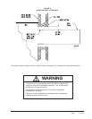
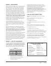
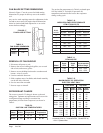
FIGURE 15
START UP LABEL
IMPORTANT
THESE PROCEDURES MUST BE
FOLLOWED AT INITIAL START UP
AND AT ANY TIME POWER HAS
BEEN REMOVED FOR 12 HOURS
OR LONGER.
TO PREVENT COMPRESSOR DAMAGE
WHICH MAY RESULT FROM THE PRESENCE
OF LIQUID REFRIGERANT IN THE
COMPRESSOR CRANKCASE:
1. Make certain the room thermostat is in the
"off" position (the compressor is not to
operate).
2. Apply power by closing the system
disconnect switch. This energizes the
compressor heater which evaporates the
liquid refrigerant in the crankcase.
3. Allow 4 hours or 60 minutes per poind of
refrigerant in the system as noted on the
unit rating plate, whichever is greater.
4. After properly elapsed time, the thermostat
may be set to operate the compressor.
5. Except as required for safety while
servicing. Do not open system
disconnect switch.
7961-061