


Manual 2100-193O
Page 2 of 26
CONTENTS
Start Up
Important Installer Note........................................ 20
Crankcase Heaters ..............................................20
Service Hints........................................................20
Sequence of Operation........................................ 20
Pressure Service Ports ........................................21
Defrost Cycle .......................................................21
Troubleshooting
Solid State Heat Pump Control
Troubleshooting Procedures................................22
Checking Temperature Sensor Outside
Unit Circuit ...........................................................23
Fan Blade Setting Dimensions ............................24
Removal of Fan Shroud .......................................24
Refrigerant Charge ..............................................24
Pressure Tables ................................................... 25
Optional Accessories ...........................................26
G
etting Other Information and Publications
For more information,
contact these publishers ........................................3
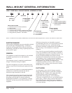
Wall Mount General Information
Heat Pump Wall Mount Model Nomenclature ........4
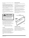
Shipping Damage ..................................................4
General .............................................................4
Duct Work ...................................................... 4 & 8
Filters .............................................................8
Fresh Air Intake......................................................8
Condensate Drain ..................................................8
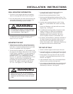
Installation Instructions
Wall Mounting Information .....................................9
Mounting the Unit................................................... 9
Top Outlet Only ......................................................9
Wiring — Main Power ..........................................15
Wiring — Low Voltage Wiring...............................15
Low Voltage Connections .................................... 15
Optional Outdoor Thermostat Applications ..........17
Thermostat Indicator ............................................19
Figures
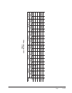
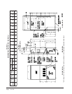
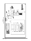
Figure 1 Unit Dimensions ...................................6
Figure 2 Fresh Air Damper Assembly .................8
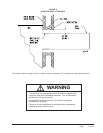
Figure 3 Mounting Instructions .........................10
Figure 4 Electric Heat Clearance ...................... 11
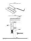
Figure 5 Attaching Top Outlet to Unit ................12
Figure 6 Top Outlet Model Mounted .................12
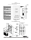
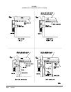
Figure 7 Wall-Mounting Instructions .................13
Figure 8 Wall-Mounting Instructions .................13
Figure 9 Common Wall-Mounting Installations .14
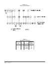
Figure 10 Low Voltage Wiring .............................16
Figure 11 Compressor Cutoff
Thermostat Wiring ..............................17
Figure 12 Compressor Cutoff
Thermostat Wiring ..............................17
Figure 13 Electric Heat Hold-Off Wiring ..............18
Figure 14 Electric Heat Hold-Off Wiring ..............18
Figure 15 Start Up Label .....................................20
Figure 16 Defrost Control Board .........................21
Figure 17 Fan Blade Setting ...............................24
Tables
Table 1 Electric Heat Table................................5
Table 2 Dimensions of Basic Unit......................6
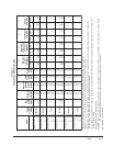
Table 3 Electrical Specifications ........................7
Table 4 Operating Voltage Range ...................15
Table 5 Thermostat Wire Size .........................16
Table 6 Wall Thermostat..................................19
Table 7 Troubleshooting ..................................22
Table 8 Fan Blade Dimensions .......................24
Table 9 Suction Line Temperatures .................24
Table 10 Indoor Blower Performance ................24
Table 11 CFM and ESP.....................................24
Table 12 Maximum ESP of Operation
Electric Heat Only ...............................24
Table 13 Cooling Pressures .............................. 25
Table 14 Heating Pressures ..............................25
Table 15 Optional Accessories ..........................26