


Manual 2100-373
Page 4
Size of unit for a proposed installation should be based
on heat loss calculation made according to methods of
Air Conditioning Contractors of America (ACCA). The
air duct should be installed in accordance with the
Standards of the National Fire Protection Association
for the Installation of Air Conditioning and Ventilating
systems of Other Than Residence Type, NFPA No.
90A, and Residence Type Warm Air Heating and Air
Conditioning Systems, NFPA No. 90B. Where local
regulations are at a variance with instructions, installer
should adhere to local codes.
DUCT WORK
Any heat pump is more critical of proper operating
charge and an adequate duct system that a straight air
conditioning unit. All duct work, supply and return,
must be properly sized for the design air flow
requirement of the equipment. Air Conditioning
Contractors of America (ACCA) is an excellent guide
Q
R
S
T
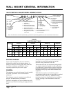
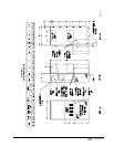
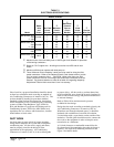
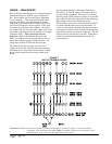
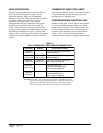
Maximum size of the time delay fuse or HACR type circuit breaker for protection
of field wiring conductors.
Based on 75° C copper wire. All wiring must conform to NEC and all local
codes.
Maximum KW that can operate with heat pump on.
These “Minimum Circuit Ampacity” values are to be used for sizing the field
power conductors. Refer to the National Electric Code (latest revision), article
310, for power conductor sizing.
CAUTION: When more than one field
power conductor circuit is run through one conduit the conductors must be
derated. Pay special attention to note 89 of table 310 regarding Ampacity
Adjustment Factors when more than 3 are in a raceway.
TIUCRICELGNIS
ledoM
detaR
stloV
dna
esahP
dleiF.oN
rewoP
stiucriC
m
muminiM
tiucriC
yticapmA
j
mumixaM
lanretxE
roesuF
tiucriC
rekaerB
k
dleiF
rewoP
eziSeriW
k
dnuorG
eziSeriW
Z0A,00A-381HW
40A
l 80A
1-802/032
1
1
1
71
83
95
52
04
06
21
01
6
21
01
01
Z0A,00A-242HW
40A
l 80A
1-802/032
1
1
1
81
93
06
52
04
06
21
01
6
21
01
01
Z0B,00B-242HW
60B
1-802/032
1
1
51
33
02
53
21
8
21
01
Z0C,00C-242HW
60C
3-064
1
1
8
71
51
02
41
21
41
21
TABLE 2
ELECTRICAL SPECIFICATIONS
to proper sizing. All duct work or portions thereof not
in the conditioned space should be properly insulated in
order to both conserve energy and prevent condensation
or moisture damage.
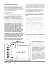
Refer to Table 10 for maximum static pressure
available for duct design.
Design the duct work according to methods given by the
Air Conditioning Contractors of America (ACCA).
When duct runs through unheated spaces, it should be
insulated with a minimum of one inch of insulation.
Use insulation with a vapor barrier on the outside of the
insulation. Flexible joints should be used to connect the
duct work to the equipment in order to keep the noise
transmission to a minimum.
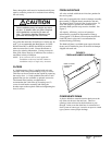
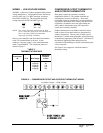
A 1/4 inch clearance to combustible material for the
first three feet of duct attached to the outlet air frame is
required. See Pages Wall Mounting Instructions and
Figure 3 for further details.