


Manual 2100-192
Page 13
IMPORTANT INSTALLER NOTE
For improved start-up performance, wash the indoor
coil with a dishwasher detergent.
CRANKCASE HEATERS
All units are provided with some form of compressor
crankcase heat.
All single and three phase models have an insertion
well-type heater located in the lower section of the
compressor housing. This is a self-regulating type
heater that draws only enough power to maintain the
compressor at a safe temperature.
Some form of crankcase heat is essential to prevent
liquid refrigerant from migrating to the compressor,
causing oil pump out on compressor start up and
possible valve failure due to compressing a liquid.
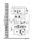
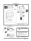
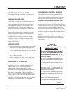
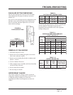
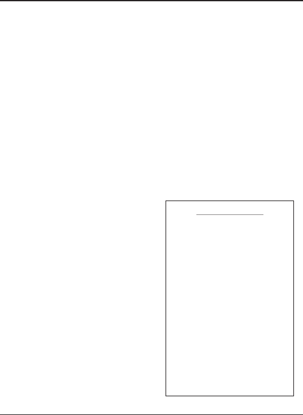
The decal in Figure 9 is affixed to all outdoor units
detailing start up procedure. This is very important.
Please read carefully.
SERVICE HINTS
1. Caution homeowner to maintain clean air filters at all
times. Also, not to needlessly close off supply and
return air registers. This reduces air flow through the
system, which shortens equipment service life as well
as increasing operating costs.
2. Check all power fuses or circuit breakers to be sure
they are the correct rating.
3. Periodic cleaning of the outdoor coil to permit full
and unrestricted airflow circulation is essential.
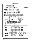
SEQUENCE OF OPERATION
Cooling—Circuit R-Y makes at thermostat pulling in
compressor contactor, starting the compressor and
outdoor motor. The G (indoor motor) circuit is
automatically completed on any call for cooling
operation or can be energized by manual fan switch on
subbase for constant air circulation. On all 230 volt
units there is a one minute off delay on the blower
motor. 460 volt models do not have an off delay. On a
call for heating, circuit R-W1 make at the thermostat
pulling in heat contact for the strip heat and blower
operation. On a call for second stage heat, R-W2 makes
bringing on second heat contactor, if so equipped.
START UP
FIGURE 9
START UP LABEL
COMPRESSOR CONTROL MODULE
The compressor control module is optional on the
models covered by this manual. The compressor control
is an anti-short cycle/lockout timer with high and low
pressure switch monitoring and alarm relay output.
Adjustable Delay On Make And Break Timer
On initial power up or any time power is interrupted to
the unit the delay on make period begins which will be
2 minutes plus 10% of the delay on break setting. When
the delay on make is complete and the high pressure
switch (and low pressure switch if employed) is closed,
the compressor contactor is energized. Upon shutdown
the delay or break timer starts and prevents restart until
the delay on break and delay on make periods have
expired.
During routine operation of the unit with no power
interruptions the compressor will operate on demand
with no delay.
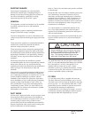
IMPORTANT
These procedures must be followed
at initial start up and at any time
power has been removed for 12
hours or longer.
To prevent compressor damage which may
result from the presence of liquid refrigerant in
the compressor crankcase:
1. Make certain the room thermostat is in the
"off" position (the compressor is not to operate).
2. Apply power by closing the system
disconnect switch. This energizes the
compressor heater which evaporates the liquid
refrigerant in the crankcase.
3. Allow 4 hours or 60 minutes per poind of
refrigerant in the system as noted on the unit
rating plate, whichever is greater.
4. After properly elapsed time, the thermostat
may be set to operate the compressor.
5. Except as required for safety while servicing,
do not open system disconnect switch
.
7961-061