


Manual 2100-234I
Page 12 of 17
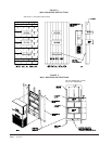
WIRING – MAIN POWER
Refer to the unit rating plate for wire sizing information
and maximum fuse or “HACR” type circuit breaker size.
Each outdoor unit is marked with a “Minimum Circuit
Ampacity”. This means that the field wiring used must
be sized to carry that amount of current. Depending on
the installed KW of electric heat, there may be two field
power circuits required. If this is the case, the unit serial
plate will so indicate. All models are suitable only for
connection with copper wire. Each unit and/or wiring
diagram will be marked “Use Copper Conductors Only”.
These instructions must be adhered to. Refer to the
National Electrical Code (NEC) for complete current
carrying capacity data on the various insulation grades of
wiring material. All wiring must conform to NEC and all
local codes.
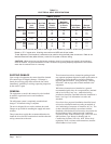
The electrical data lists fuse and wire sizes (75°C copper)
for all models, including the most commonly used heater
sizes. Also shown are the number of field power circuits
required for the various models with heaters.
The unit rating plate lists a “Maximum Time Delay Relay
Fuse” of “HACR” type circuit breaker that is to be used
with the equipment. The correct size must be used for
proper circuit protection and also to assure that there will
be no nuisance tripping due to the momentary high
starting current of the compressor motor.
PATEGNAR
042-352612
802-022781
NOTE: The voltage should be measured at the field power
connection point in the unit and while the unit is
operating at full load (maximum amperage
operating condition).
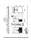
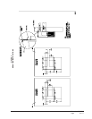
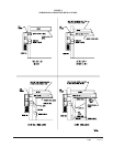
Five (5) wires should be run from thermostat subbase to
the 24V terminal board in the unit. A five conductor, 18
gauge copper, color-coded thermostat cable is
recommended. The connection points are shown in
Figure 7.
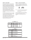
WIRING – LOW VOLTAGE WIRING
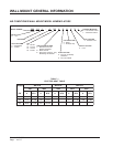
230/208, 1 phase equipment use dual primary voltage
transformers. All equipment leaves the factory wired on
240V tap. For 208V operation, reconnect from 240V to
208V tap. The acceptable operating voltage range for the
240 and 208V taps are:
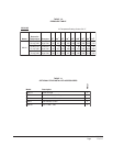
remrofsnarT
AVALFeguaGeriW
ecnatsiDmumixaM
teeFni
043.2
eguaG02
eguaG81
eguaG61
eguaG41
eguaG21
54
06
001
061
052
TABLE 3
THERMOSTAT WIRE SIZE
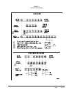
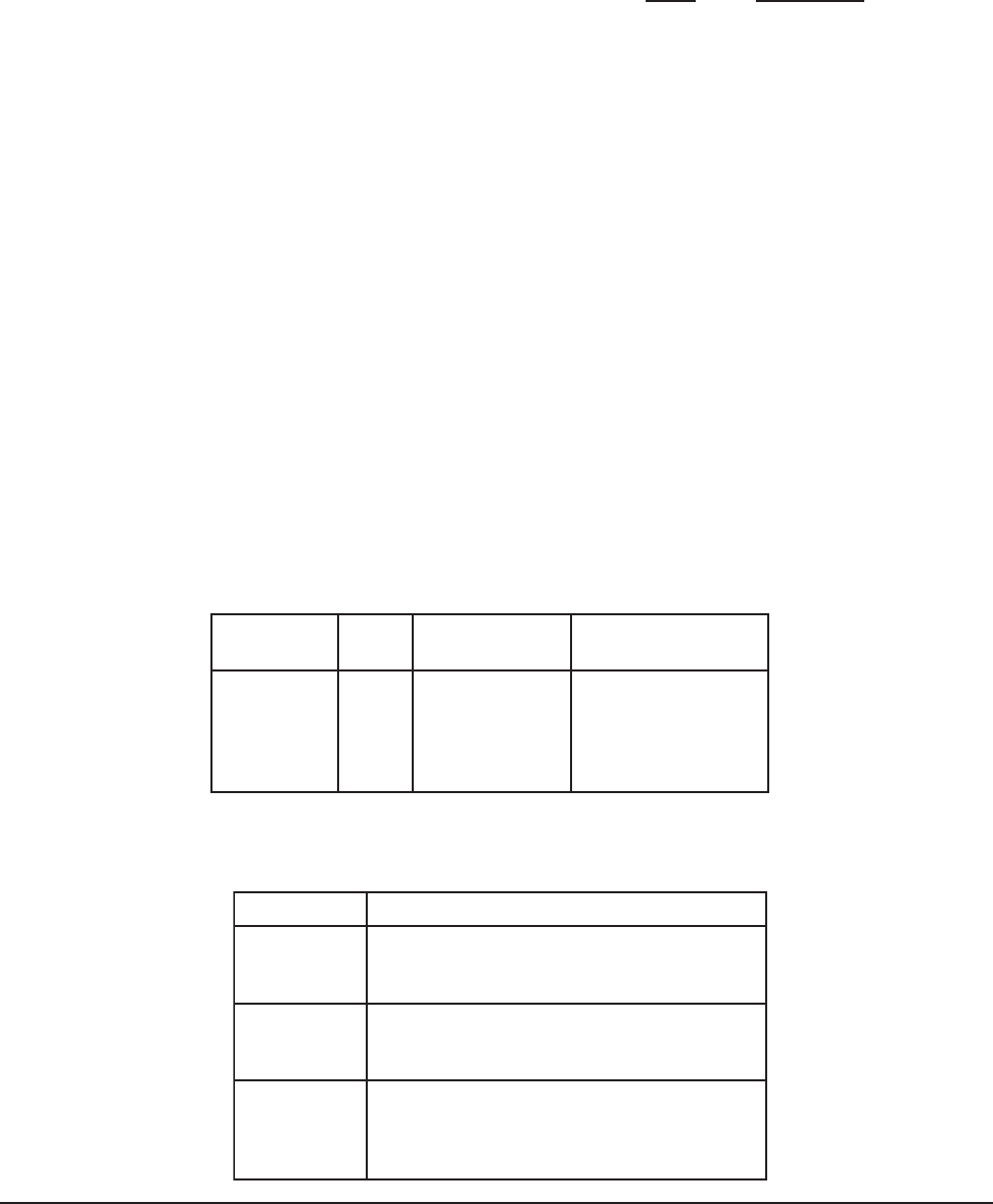
TABLE 4
WALL THERMOSTAT
tatsomrehTserutaeFetanimoderP
750-3048
3511D0225HT
taeHegats1,looCegats1
elbammargorP-noNcinortcelE
revoegnahclaunaMrootuA
850-3048
1511D0225HT
taeHegats2,looCegats2
elbammargorP-noNcinortcelE
revoegnahclaunaMrootuA
060-3048
)544-0211(
taeHegats3;looCegats3
cinortcelEelbammargorP-noN/elbammargorP
lanoitnevnoCroPH
revoegnahclaunaMrootuA