


Manual 2100-509E
Page 8 of 17
INSTALLATION INSTRUCTIONS
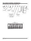
WALL MOUNTING INFORMATION
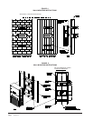
1. These units are secured by wall mounting brackets
which secure the unit to the outside wall surface at
both sides.
2. On wood frame walls, the wall construction must be
strong and rigid enough to carry the weight of the
unit without transmitting any unit vibration.
3. Concrete block walls must be thoroughly inspected
to insure that they are capable of carrying the weight
of the installed unit.
MOUNTING THE UNIT
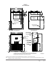
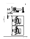
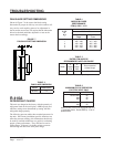
1. Two holes, for the supply and return air openings,
must be cut through the wall as shown in Figure 3.
2. Locate and mark lag bolt locations, if desired. See
Figure 3.
3. Hook top rain ashing under back bend of top. Top
rain ashing is shipped attached to the back of the
unit on the right side.
4. Position unit in opening and secure with 5/16 lag
bolts; use 7/8 inch diameter at washers on the lab
bolts.
5. Secure rain ashing to wall and caulk across entire
length of top. See Figure 3.
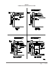
6. For additional mounting rigidity, the return air
and supply air frames or collars can be drilled
and screwed or welded to the structural wall itself
(depending upon wall construction). Be sure to
observe required clearance if combustible wall.
7. On side-by-side installations, maintain a minimum
of 20 inches clearance on right side to allow access
to control panel and allow proper airow to outdoor
coil. Additional clearance may be required to meet
local or national codes.