


Manual 2100-509E
Page 7 of 17
DUCT WORK
All duct work, supply and return must be properly sized
for the design air ow requirement of the equipment.
Air Conditioning Contractors of America (ACCA) is
an excellent guide to proper sizing. All duct work or
portions thereof not in the conditioned space should be
properly insulated in order to both conserve energy and
prevent condensation or moisture damage.
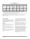
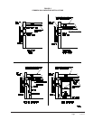
Refer to Table 6 for maximum static pressure available
for duct design.
Design the duct work according to methods given by
the Air Conditioning Contractors of America (ACCA).
When duct runs through unheated spaces, it should be
insulated with a minimum of one inch of insulation.
Use insulation with a vapor barrier on the outside of the
insulation. Flexible joints should be used to connect the
duct work to the equipment in order to keep the noise
transmission to a minimum.
Ducts through the walls must be insulated and all joints
taped or sealed to prevent air or moisture entering the
wall cavity.
Some installations may not require any return air duct.
It is recommended that on this type of installation that
a lter grille be located in the wall. Filters must be of
sufcient size to allow a maximum velocity of 400 FPM.
NOTE: If no return air duct is used, applicable
installation codes may limit this cabinet to
installation only in a single story structure.
FILTERS
A one inch throwaway lter is supplied with each unit.
The lter slides into position making it easy to service.
This lter can be serviced from the outside by removing
the service door. A 2-inch pleated lter is also available
as an optional accessory. The internal lter brackets are
adjustable to accommodate the 2-inch lter by bending
the metal tabs holding the 1-inch lter down. There are
two tabs on each side of the lter.
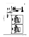
FRESH AIR INTAKE
All units are built with fresh air inlet slots punched in the
service panel.
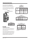
If the unit is equipped with a fresh air damper assembly,
the assembly is shipped already attached to the unit. The
damper blade is locked in the closed position. To allow
the damper to operate, the maximum and minimum blade
position stops must be installed. See Figure 2.
All capacity, efciency and cost of operation information
as required for Department of Energy “Energyguide”
Fact Sheets is based upon the fresh air blank-off plate
in place and is recommended for maximum energy
efciency.
The blank-off plate is available upon request from the
factory and is installed in place of the fresh air damper
shipped with each unit.
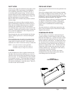
CONDENSATE DRAIN
This unit employs an automatic condensate disposal
system consisting of a base drain pan, drain valve and
fan blade with slinger ring. A plastic drain hose extends
from the evaporator drain pain at the top of the unit to
the base drain pan at the bottom. At temperatures above
40°, the drain valve located between the condenser coil
and fan shroud is closed allowing water to build up in
the base to a height of 5/8" to 3/4". The fan blade with
slinger then rotates in this water and throws the water
onto the condenser coil. This disposes of the water by
evaporating it on the hot condenser.
At temperatures below 40°, the drain valve opens
draining the base pan and preventing freeze ups that
could damage the coil or fan blade.
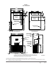
FIGURE 2
FRESH AIR DAMPER