


Manual 2100-420H
Page 31 of 34
TROUBLESHOOTING GE ECM
™
MOTORS CONT’D.
Replacing ECM Control Module
To replace the control module for the GE variable-speed indoor blower
motor you need to take the following steps:
1. You MUST have the correct replacement module. The controls are
factory programmed for specific operating modes. Even though they look
alike, different modules may have completely different functionality.
USING THE WRONG CONTROL MODULE VOIDS ALL PRODUCT
WARRANTIES AND MAY PRODUCE UNEXPECTED RESULTS.
2. Begin by removing AC power from the furnace or air handler being
serviced. DO NOT WORK ON THE MOTOR WITH AC POWER
APPLIED. To avoid electric shock from the motor’s capacitors, disconnect
power and wait at least 5 minutes before opening motor.
3. It is usually not necessary to remove the motor from the blower
assembly. However, it is recommended that the whole blower assembly,
with the motor, be removed from the furnace/air handler. (Follow the
manufacturer’s procedures). Unplug the two cable connectors to the motor.
There are latches on each connector. DO NOT PULL ON THE WIRES.
The plugs remove easily when properly released.
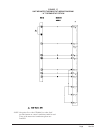
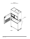
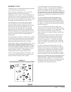
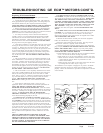
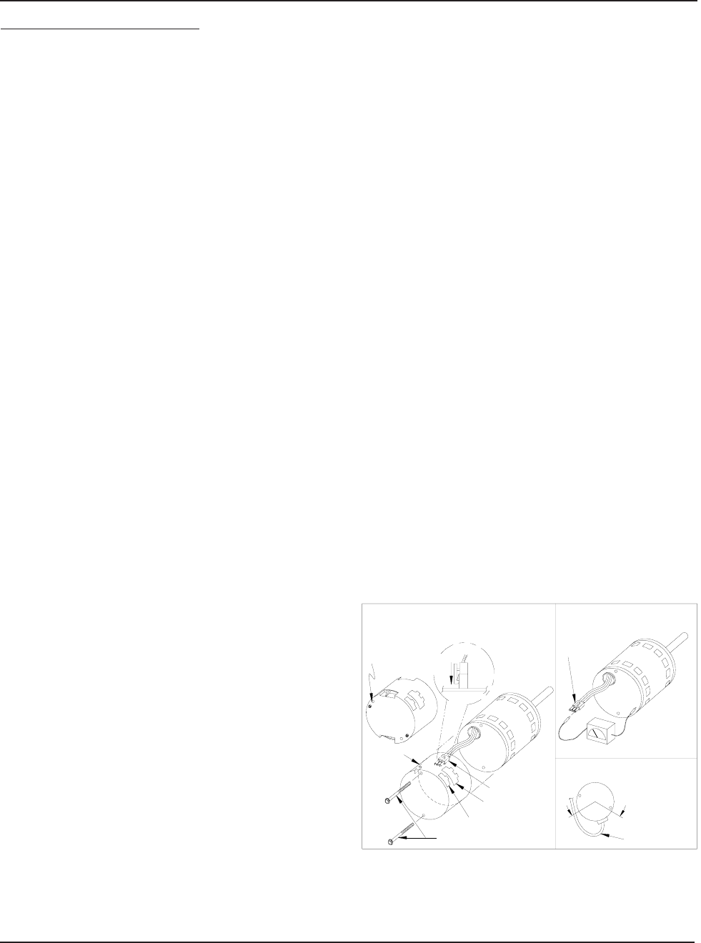
4. Locate the two standard
¼" hex head bolts at the rear of the control
housing (at the back end of the control opposite the shaft end). Refer
to Figure 23. Remove these two bolts from the motor and control
assembly while holding the motor in a way that will prevent the motor
or control from falling when the bolts are removed. If an ECM2.0
control is being replaced (recognized by an aluminum casting rather
that a deep-drawn black steel can housing the electronics), remove
only the hex-head bolts. DO NOT REMOVE THE TORX-HEAD
SCREWS.
5. The control module is now free of mechanical attachment to the
motor endshield but is still connected by a plug and three wires inside
the control. Carefully rotate the control to gain access to the plug at
the control end of the wires. With thumb and forefinger, reach the
latch holding the plug to the control and release it by squeezing the
latch tab and the opposite side of the connector plug and gently pulling
the plug out of the connector socket in the control. DO NOT PULL
ON THE WIRES. GRIP THE PLUG ONLY.
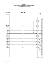
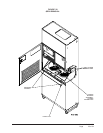
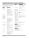
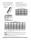
6. The control module is now completely detached from the motor.
Verify with a standard ohmmeter that the resistance from each motor
lead (in the motor plug just removed) to the motor shell is >100K
ohms. Refer to Figure 24. (Measure to unpainted motor end plate.) If
any motor lead fails this test, do not proceed to install the control
module. THE MOTOR IS DEFECTIVE AND MUST BE
REPLACED. Installing the new control module will cause it to fail
also.
7. Verify that the replacement control is correct for your
application. Refer to the manufacturer's authorized replacement list.
USING THE WRONG CONTROL WILL RESULT IN
IMPROPER OR NO BLOWER OPERATION. Orient the control
module so that the 3-wire motor plug can be inserted into the socket in
the control. Carefully insert the plug and press it into the socket until
it latches. A SLIGHT CLICK WILL BE HEARD WHEN
PROPERLY INSERTED.
Finish installing the replacement control per
one of the three following paragraphs, 8a, 8b or 8c.
8a. IF REPLACING AN ECM 2.0 CONTROL (control in cast
aluminum can with air vents on the back of the can) WITH AN ECM
2.3 CONTROL (control containing black potting for water protection
in black deep-drawn steel case with no vents in the bottom of the can),
locate the two through-bolts and plastic tab that are packed with the
replacement control. Insert the plastic tab into the slot at the perimeter
of the open end of the can so that the pin is located on the inside of the
perimeter of the can. Rotate the can so that the tab inserts into the tab
locater hole in the endshield of the motor. Using the two through-
bolts provided with the replacement control, reattach the can to the
motor.
THE TWO THROUGH-BOLTS PROVIDED WITH THE
REPLACEMENT ECM 2.3 CONTROL ARE SHORTER THAN
THE BOLTS ORIGINALLY REMOVED FROM THE ECM 2.0
CONTROL AND MUST BE USED IF SECURE ATTACHMENT
OF THE CONTROL TO THE MOTOR IS TO BE ACHIEVED.
DO NOT OVERTIGHTEN THE BOLTS.
8b. IF REPLACING AN ECM 2.3 CONTROL WITH AN ECM
2.3 CONTROL, the plastic tab and shorter through-bolts are not needed.
The control can be oriented in two positions 180° apart. MAKE SURE
THE ORIENTATION YOU SELECT FOR REPLACING THE
CONTROL ASSURES THE CONTROL'S CABLE CONNECTORS
WILL BE LOCATED DOWNWARD IN THE APPLICATION SO
THAT WATER CANNOT RUN DOWN THE CABLES AND INTO
THE CONTROL. Simply orient the new control to the motor's
endshield, insert bolts, and tighten. DO NOT OVERTIGHTEN THE
BOLTS.
8c. IF REPLACING AN ECM 2.0 CONTROL WITH AN ECM 2.0
CONTROL (It is recommended that ECM 2.3 controls be used for all
replacements), the new control must be attached to the motor using
through bolts identical to those removed with the original control. DO
NOT OVERTIGHTEN THE BOLTS.
9. Reinstall the blower/motor assembly into the HVAC equipment.
Follow the manufacturer's suggested procedures.
10. Plug the 16-pin control plug into the motor. The plug is keyed.
Make sure the connector is properly seated and latched.
11. Plug the 5-pin power connector into the motor. Even though the
plug is keyed, OBSERVE THE PROPER ORIENTATION. DO NOT
FORCE THE CONNECTOR. It plugs in very easily when properly
oriented. REVERSING THIS PLUG WILL CAUSE IMMEDIATE
FAILURE OF THE CONTROL MODULE.
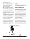
12.
Final installation check. Make sure the motor is installed as follows:
a.Unit is as far INTO the blower housing as possible.
b.Belly bands are not on the control module or covering vent holes.
c.Motor connectors should be oriented between the 4 o’clock and 8
o’clock positions when the blower is positioned in its final
location and orientation.
d.Add a drip loop to the cables so that water cannot enter the motor
by draining down the cables. Refer to Figure 25.
The installation is now complete. Reapply the AC power to the HVAC
equipment and verify that the new motor control module is working
properly. Follow the manufacturer's procedures for disposition of the old
control module.
Motor
Motor OK when
R > 100k ohm
ECM 2.0
Only remove
Hex Head Bolts
Connector Orientation
Between 4 and 8 o'clock
Drip Loop
Back of
Control
Figure 5
Winding Test
Figure 4
Note:
Use the shorter
bolts and
alignment pin
supplied when
replacing an
ECM 2.0
control.
Figure 3
ECM
2.3/2.5
Power Connector
(5-pin)
Control Connector
(16-pin)
Hex-head Screws
Motor Connector
(3-pin)
Motor Connector
(3-pin)
Control Disassembly
Drip Loop
Push until
Latch Seats
Over Ramp
From Motor
Circuit
Board
Figure 24
Figure 23
Figure 25