


CONTENTS
Getting Other Informations and Publications
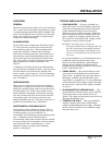
General Instructions
Important ................................................................ 2
Shipping Damage .................................................... 2
General ................................................................ 2
Field Installed Heater Packages (Optional) ............. 2
Installation
Location ................................................................ 9
Typical Installations ................................................. 9
Condensate Drain Trap ......................................... 14
Air Filters .............................................................. 14
Wiring – Main Power ............................................. 15
Wiring – 24V Low Voltage Control Circuit ............. 15
Transformer Taps ................................................... 15
Thermostats ........................................................... 15
Start Up and Operation
Three Phase Scroll Compressor Start Up
Information............................................................. 17
Sequence of Operation.......................................... 17
Start Up Notes ....................................................... 17
Indoor Blower Motor .............................................. 17
Compressor Control Module .................................. 17
Adjustments ........................................................... 18
Service and Troubleshooting
Service Hints ......................................................... 19
Pressure Service Ports .......................................... 19
Refrigerant Charge ................................................ 19
Fan Blade Settings ................................................ 19
Suction and Discharge Tube Brazing .................... 20
Pressure Table....................................................... 14
Wiring Diagrams ............................................... 15-16
Troubleshooting ECM Blower Motors ............. 23-24
Figures
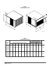
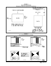
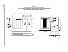
Figure 1 Unit Dimensions ...................................... 8
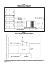
Figure 2 Slab Mounting at Ground Level ............ 10
Figure 3 Airflow and Service Access
Clearances............................................ 10
Figure 4 Roof Top Application ..............................11
Figure 5 Elevated Mounting Platforms .................11
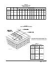
Figure 6 Prefabricated Rood Curb
Specifications........................................ 12
Figure 7 Field Fabricated Curbing....................... 13
Figure 8 Condensate Drain Trap ......................... 14
Figure 9 Low Voltage Wiring ............................... 16
Figure 10 Fan Blade Setting ................................. 19
Figure 11 Brazing Diagram ................................... 20
Tables
Table 1 Rated CFM & ESP .................................. 2
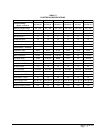
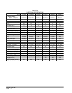
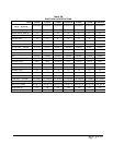
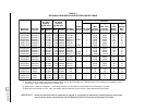
Table 2 Electrical Specifications .......................... 3
Table 2A Electrical Specifications .......................... 4
Table 2B Electrical Spedifications .......................... 5
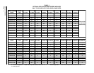
Table 3 Option Field Installed Heater Packages . 6
Table 4 Electric Heater Table............................... 8
Table 5 Unit Dimensions ...................................... 5
Table 6 Roof Curb Details ................................. 13
Table 7 Dimension for Figure 7.......................... 13
Table 8 Filter Requirements & Sizes ................. 14
Table 9 Thermostat Wire Size ........................... 15
Table 10 Wall Thermostat and Subbase
Combinations ........................................ 15
Table 11 Suction Line Temperatures ................... 19
Table 12 Fan Blade Setting Dimensions.............. 19
Table 13 Indoor Blower Performance .................. 20
Table 14 Pressure Table ...................................... 21
Table 14A Pressure Table ...................................... 22