


Manual 2100-571A
Page 2 of 31
CONTENTS
Econ. Failure & 2-Compressor Run Alarm ........... 24
Alarm Wiring ...........................................................24
2nd Stage Cooling Alarm ....................................... 25
Refrigerant Pressure Alarms ................................. 25
Emergency Ventilation Sequence ......................... 25
Programming Instructions .....................................28
Figures
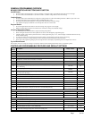
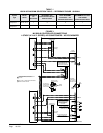
Figure 1 Controller Connections 1-Stage (H**A/L
Series) A/C w/No Economizers ................................16
Figure 2 Controller Connections 2-Stage (HA*S/HL*S
Series) A/C - No Economizers ..................................17
Figure 3 Controller Connections 1-Stage (H**A/L
Series) A/C - No Econ. w/Alarm Board & CB4000
Comm. Board ...........................................................18
Figure 4 Controller Connections 2-Stage (HA*S/HL*S
Series) A/C - No Econ. w/Alarm Board & CB4000
Comm. Board ...........................................................19
Figure 5 Controller Connections 1-Stage (H**A/L
Series) A/C w/ECONWMT Econ. ..............................20
Figure 6 Controller Connections 2-Stage (HA*S/HL*S
Series A/C w/ECONWMT Econ. ............................... 21
Figure 7 Controller Connections 1-Stage (H**A/L
Series) A/C w/ ECONWMT Econ. & w/Alarm Board &
CB4000 Comm. Board ............................................22
Figure 8 Controller Connections 2-Stage (HA*S/HL*S
Series A/C w/ECONWMT Econ. & w/Alarm Board &
CB4000 Comm. Board ............................................23
— — — Alarm LED Display Board ........................24
Figure 9 Alarm Board Connections for Normally
Closed "NC" Open-On-Alarm Strategy .....................26
Figure 10 Alarm Board Connections for Normally Open
"NO" Close-On-Alarm Strategy ................................27
— — — MV4000 Label .........................................29
Figure 11 Parts List Description Diagram ................ 30
Tables
Table 1 Hook-Up Diagram Selection .................... 16
Table Parts List .................................................31
Getting Other Information and Publications 3
MV4000 General Information
Shipping Damage....................................................4
General ...................................................................4
Theory of Operation ................................................4
ControllerCertications ...........................................4
Specications/Features for MV4000 Series Controller
MV4000 Controller ..................................................5
Mounting the Controller
Installation Instructions............................................5
Temperature Sensors
Two Optional Sensor Inputs .................................... 5
Temperature Sensor Logic
Using Multiple Sensors ...........................................5
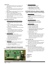
Controller Input/Output Specications
MV4000 Controller Connections .............................6
Located in the MV4000 Panel Box
Unit #1 & Unit #2 Terminal Block .............................6
Specications/Features for Alarm Boards
MV4000-B with Enhanced Version Alarm ...............7
Low Voltage Field Wiring
Circuitry in the MV4000 ...........................................7
Controller Grounding
Earth ground ...........................................................7
Controller Power-Up
Time Delay on Power-Up ........................................7
Fire Suppression Circuit
Disabling the MV4000 ............................................. 8
Staging Delay Periods
Stages 1 - 4 .............................................................8
Blower Operation
Various Blower Options ........................................... 8
Advance (Swap) Lead/Lag Unit Feature
Manual Switching of Units .......................................8
Accelerate Timer Feature
Testing the Timer Function ...................................... 8
General Programming Overview
Buttons & Function ..................................................9
Humidity Control Option
Adding Optional Humidity Control ......................... 10
Cooling Operating Sequences
forAlternatingLead/Lag/Lead/LagCong .......10-11
Cooling Operating Sequences
forNon-AltLead/Lead/Lag/LagCong ............11-12
Heating Sequence of Operation .......................12-13
Specications Opt. Remote Comm. Board
CB4000 Communications Board ...................... 13-14
Controller Wiring
Refer to Connection Diagram................................15
Security (Locking) Feature
Locking and Unlocking the MV4000......................15
Generator Run / Economizer Shutdown Feature
Standby Generator Disable Operation .................. 15
Backup DC Power Connection
Input Connections Available ..................................15