


Manual 2100-571A
Page 10 of 31
HUMIDITY CONTROL OPTION
Note: This function is not available if controller is
congured for heat pump.
The standard air conditioning system can be adapted
to perform dehumidication control by addition of
a simple humidity controller that closes-on-rise, and
is connected to terminals H1 and H2 on the main
controller board. Recommended Bard Part #8403-038
(H600A 1014). Both HVAC units must be equipped
with electric heat for this sequence to work properly.
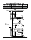
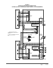
See appropriate connection diagram - Figures 1 - 12 for
this connection:
1. Temperature control always has priority over
dehumidication. If there is any stage of cooling
demand active, the dehumidication sequence is
locked out.
2. If all stages of cooling are satised, and relative
humidity is above the set point of humidity
controller:
a. The green “Dehumid. Operation” light will come
on, and the lag unit compressor and blower will
operate until the set point of humidity controller
is satised (or cancelled by a call for cooling).
b. If the space temperature drops to 67F, the electric
heater of the lead unit will cycle to help maintain
building temperature. It will cycle off at 69F.
c. If space temperature drops to 64F, the Stage 2
Heating light will come on and the lag unit
compressor operating for dehumidication mode
will cycle off until the building temperature rises
above 65F from 1st stage heat and building load.
The green “Dehumid. Operation” light stays on
during this sequence, and when Stage 2 Heating
light is Off, the compressor is On. The electric
heater in lag unit is locked out in
dehumidication mode.
Lag unit outputs G, Y1 and Y2 are all switched on
during dehumidication sequence. This is true for both
alternating and non-alternating controller congurations.
COOLING OPERATING SEQUENCES FOR
ALTERNATING LEAD/LAG/LEAD/LAG
CONFIGURATION
1. 1-Stage Compressor Units No Economizer
1
st
stage cooling set point is the setting (SP) input
into the controller. Factory default is 77F (25C).
On a call for cooling the blower of the lead unit
will come on immediately (if not already on – See
Blower Operation), and the Stage 1 LED will blink
for 10-seconds before going solid, at which time the
compressor will start.
2
nd
cooling set point is 4F (default setting, user
selectable 2-6F) warmer than Stage 1. On a call for 2
nd
Stage cooling the blower of the lag unit is turned on (if
not already on – See Blower Operation), and the Stage
2 LED will blink for 10-seconds before going solid, at
which time the compressor will start.
3
rd
and 4
th
stages are functional outputs but there is
nothing to be controlled.
2. 2-Stage Compressor Units No Economizer
1
st
stage cooling set point is the setting (SP) input into
the controller. Factory default is 77F (25C). On a call
for cooling the blower of the lead unit will come on
immediately (if not already on – See Blower Operation),
and the Stage 1 LED will blink for 10-seconds before
going solid, at which time the lead unit compressor will
start in compressor Stage 1 partial capacity operation.
2
nd
cooling set point is 4F (default setting, user selectable
2-6F) warmer than Stage 1. On a call for 2
nd
Stage
cooling the blower of the lag unit is turned on (if not
already on – See Blower Operation), and the Stage 2 LED
will blink for 10-seconds before going solid, at which
time the lag unit compressor will start in compressor
Stage 1 partial capacity operation.
3
rd
cooling set point is 2F (default setting, user selectable
2-3F) warmer than Stage 2. On a call for 3
rd
Stage
cooling the Stage 3 LED comes on solid (no delay), and
the lead unit compressor will switch to compressor Stage
2 full capacity operation.
4
th
cooling set point is 2F (default setting, user selectable
2-3F) warmer than Stage 3. On a call for 4th Stage
cooling the Stage 4 LED comes on solid (no delay), and
the lag unit compressor will switch to compressor Stage 2
full capacity operation.
Humidity controller set point should be in 50-60%
relative humidity area: Setting controller to lower
settings will result in excessive operating time
and operating costs for the electric reheat, and in
extreme cases could cause evaporator (indoor)
coil freeze-up if there are periods of light internal
equipment (heat) loading.
CAUTION