


Snifit
Model 50
Carbon Monoxide Analyzer
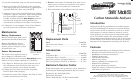
Introduction
Designed for HVAC professionals and utility person-
nel, the Snifit Model 50 Analyzer is ideal for measur-
ing low levels of CO in ambient air such as in rooms
and garages, or around registers, furnaces, stoves,
water heaters, and other types of combustion appli-
ances. The Snifit samples the surrounding air and
shows the detected concentration of CO on its Liquid
Crystal Display. The Snifit is not intended to be used in
flue gases or in temperatures exceeding 104 °F (40 °C).
Features
• Measures and displays 0 to 1999 ppm CO in room air
• Sensitive CO sensor will last up to 2 years
• Backlight for viewing in dark areas
• Compact pocket size
• Low battery indication
• Manual zero adjust
• Factory calibrated on 100 ppm CO
• Simple field calibration
• Auto power-off after 35 minutes
• Single 9V battery (included) provides at least
1500 hours of operation
Bacharach, Inc.
621 Hunt Valley Circle, New Kensington, PA 15068
Ph: 724-334-5000 • Fax: 724-334-5001 • Toll Free: 800-736-4666
Website: www.bacharach-inc.com • E-mail: help@bacharach-inc.com
Printed in U.S.A. ® Registered trademarks
Instruction 19-9201
Rev. 3 – June 1999
- 5 - - 6 -
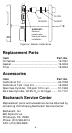
Replacement Parts
Item Part No.
CO Sensor and Gasket ...................................... 19-7061
Filter ................................................................... 19-3244
Accessories
Item Part No.
Calibration Kit ................................................... 24-7059
Calibration Tool / Cup Kit ................................ 19-3242
Span Gas Cylinder, 100 ppm CO in air ............ 51-1994
Zero Gas Cylinder, 20.9% O
2
in Nitrogen ........ 51-7131
Bacharach Service Center
Replacement parts and accessories can be obtained by
contacting the following Bacharach Service Center:
Bacharach, Inc., 625 Alpha Drive
Pittsburgh, PA 15238
Phone: (412) 963-2214 FAX: (412) 963-2606
3. Push the Calibration Cup over the sensor housing.
4. Attach a CO Span Gas Cylinder to the regulator.
Then apply span gas to the sensor by adjusting the
regulator knob for a flow rate of 2 SCFH.
5. Allow span gas to flow until the displayed reading
stabilizes – approx. 3 minutes. Then, using Calibra-
tion Tool 06-9453 (supplied in Calibration Tool /
Cup Kit 19-3242), turn the Span Adjust potentiom-
eter until the displayed reading matches the
concentration stamped on the Span Gas Cylinder.
6. Calibration is now complete. Turn off the Regula-
tor and remove the calibration equipment.
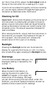
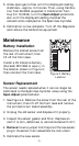
Maintenance
Battery Replacement
Remove slotted screw from rear of
instrument; then lift off front case.
Replace 9V Alkaline battery
(Duracell MN1604 or equiv.) in
location shown in Figure 3; then
reinstall front case.
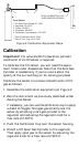
Sensor Replacement
The sensor needs replaced when it
can no longer be calibrated to the
Span Gas Cylinder value using the Span Adjust potenti-
ometer, or if it no longer responds to a CO source.
1. See Figure 4. Remove the screw from the rear of
the instrument; then lift off the front case and
remove the printed circuit board assembly.
2. Unplug the old sensor and remove its gasket.
Discard both items properly.
3. Inspect the sensor filter. Replace the filter if it has
become contaminated with dirt.
Figure 4. Sensor Installation
C O
S E N S O R
G A S K E T
F I L T E R
W A R N I N G !
R e m o v e ju m p e r - w i r e
( if i n s t a lle d ) f r o m p in s
b e f o r e in s t a ll a t io n
®
4. Remove wire-jumper (if installed) from pins of new
sensor; plug in sensor and install the new gasket
supplied; then reassemble the instrument.
5. Wait 30 minutes; then calibrate the new sensor.
Figure 3. Battery
Location