


AXIS T90C10/T90C20 Installation Guide Page 11
ENGLISH
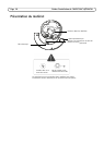
AXIS T90C10
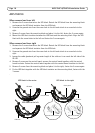
When camera lens faces left
1. Remove 2 screws located on the top on either side of the LED block and detach the LED block.
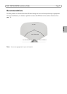
2. Move the ferrite to the center (see image below).
3. Remove 2 screws on the control board and fasten the control board to the right.
4. Align the LED block with the screw holes to the left and fasten the 2 screws again.
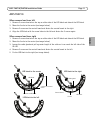
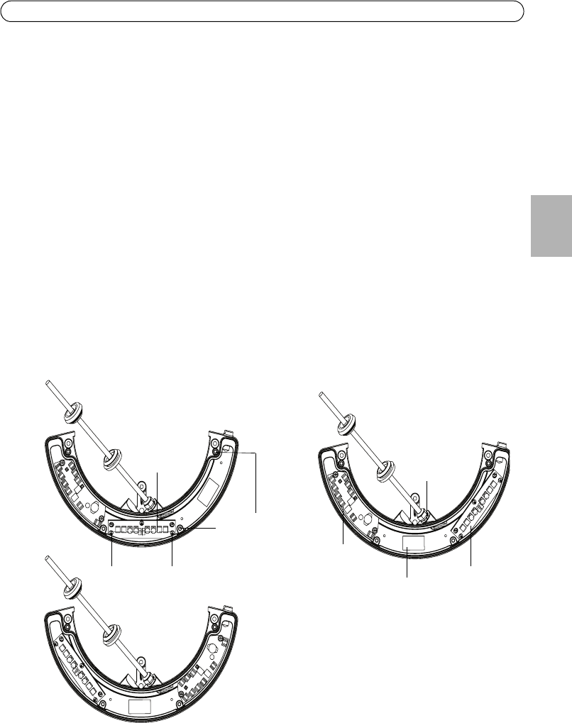
When camera lens faces right
1. Remove 2 screws located on the top on either side of the LED block and detach the LED block.
2. Move the ferrite to the center (see image below).
3. Loosen the cable gland and pull a greater length of the cable so it can reach the left side of the
IR-LED.
4. Remove 2 screws on the control board and fasten the control board to the left.
5. Fix the LED block to the right (see image below).
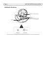
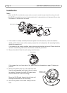
LED block
2 screws on LED block
2 screws on control
board
LED block
Control board
Cable gland
Ferrite
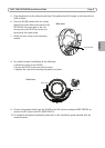
LED block to the center
LED block to the right
LED block to the left