


Page 14 AXIS Q7401 Installation Guide
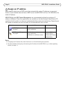
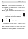
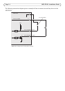
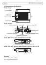
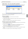
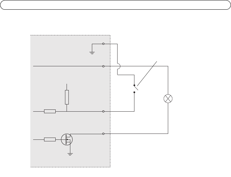
The following connection diagram gives an example of how to connect an auxiliary device to the
AXIS Q7401.
1
2
E.g. push button
I/O 3 configured as input
I/O 4 configured as output
* Note: Same voltage as pin 2 of the power connector
AXIS Q7401
3.3V
*12V max 100mA
D
S
G