


AXIS Q7401 Installation Guide Page 13
ENGLISH
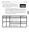
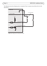
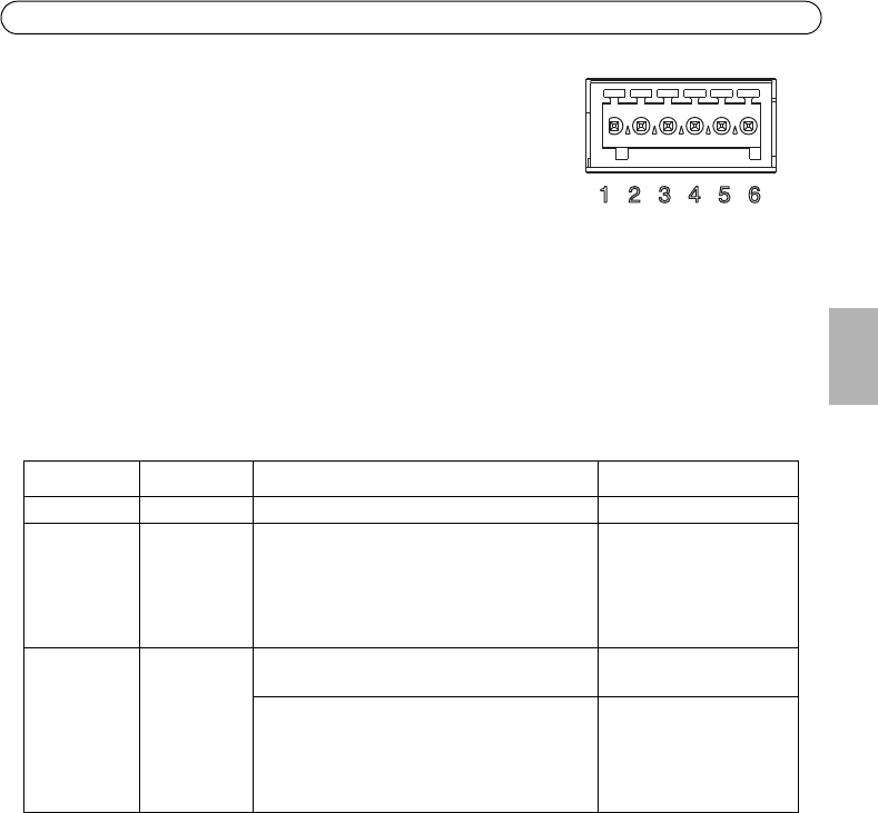
I/O terminal connector - Used in applications for e.g. motion
detection, event triggering, time lapse recording and alarm
notifications. In addition to an auxiliary power and a GND pin, the
AXIS Q7401 has 4 pins that can be configured as either input or out
put. These pins provide the interface to:
• Transistor output - For connecting external devices
such as relays and LEDs. Connected devices can be activated by AXIS VAPIX API, output
buttons on the Live View page or by an Event Type. The output will show as active
(shown under Event Configuration > Port Status) if the alarm device is activated.
• Digital input - An alarm input for connecting devices that can toggle between an open
and closed circuit, for example: PIRs, door/window contacts, glass break detectors, etc.
When a signal is received the state changes and the input becomes active (shown
under Event Configuration > Port Status.).
Function Pin number Notes Specifications
GND 1 Ground
12VDC
Power
2 Can be used to power auxiliary equipment.
Notes:
• This pin can only be used as power out.
• Same voltage as pin 2 of the power
connector.
Max load = 100mA
Configurable
(Input or
Output)
3 - 6 Digital input - Connect to GND to activate, or
leave floating (or unconnected) to deactivate.
Min input = - 40V DC
Max input = + 40V DC
Digital output - Uses an open-drain NFET
transistor with the source connected to GND.
If used with an external relay, a diode must
be connected in parallel with the load, for
protection against voltage transients.
Max load = 100mA
Max voltage = + 40V DC