


Chapter 2 Installation
P116T Stackable Switch Installation Guide 9
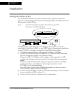
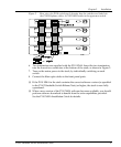
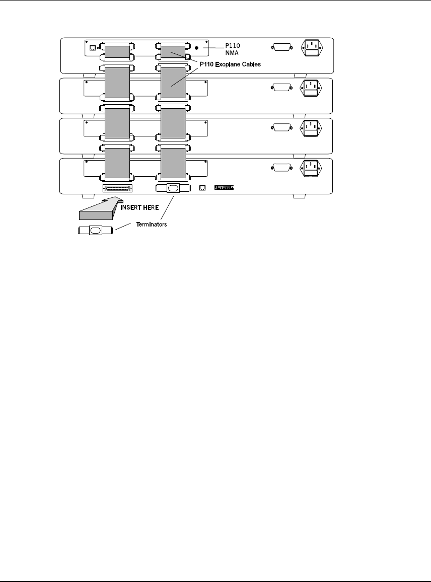
Figure 2 Rear view of a P110 switch stack, showing how the switches are linked via
the P110 Exoplane cables. A P110 NMA resides in the uppermost switch.
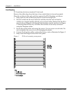
6. Two terminators are supplied with the P110 NMA. Insert the two terminators
into the lowest two connectors at the bottom of the stack, as shown in Figure 2.
7. Turn on the mains power to the stack, by individually switching on each
switch.
8. Connect the fiber-optic cables to the front panel ports.
If the P110 NMA in the stack contains the correct software version (as specified
in the P116T Stackable Switch Release Note) or higher, the stack is now fully
operational.
When a new version of the P110 NMA software becomes available, you should
perform software download to benefit from the extra capabilities provided.
See the P110 NMA Installation Guide for details.