Daisy-chaining Mixers
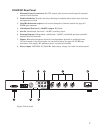
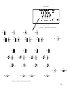
When more than four microphones are needed, it is possible to daisy-chain multiple
SmartMixers together through the Link In/Out connectors on their back panels (Fig. 2).
Connect Mixer #1 Link Out jack to Mixer #2 Link In jack, etc. Mixer #1 output contains only
audio from the first four microphones; Mixer #2 output then contains audio from all the
microphones plugged into Mixer #1 and the microphones plugged into Mixer #2. The last
mixer in the chain contains audio from all preceding mixers. The combined output is then
taken from the last mixer in the chain. Because lockout information is passed between mixers
through Link In/Out, the last-microphone-on condition is not violated. Thus only one
microphone per installation will stay on when no one is speaking.
Note that one or more mixers can be switched to “Manual” mode without affecting the
automatic operation of any other mixers in the chain.
NOMA information is passed between AT-MX351 mixers through Link In/Out. If AT-MX351
mixers are linked with AT-MX341 and/or AT-MX341a mixers, the NOMA function will pass
through the AT-MX341(a) models but their mics will not be included in the NOMA calculation.
Rack Mounting
Provided with each mixer are two rack ears and six self-tapping screws to attach the ears to
the unit, which allow the unit to be mounted in a 1U rack space.
Security Caps
For permanent installations where microphone selections, positions and acoustic conditions
are constant, it may be advantageous to remove the front panel knobs and install security
caps to prevent unauthorized adjustments. To install, simply press the caps into place,
covering the desired control(s). The system should be tested carefully before installing the
security caps because they are intended to be “permanent” and are very difficult to remove.
If removal of installed security caps becomes necessary, unplug the mixer, remove the two
screws on each side of the unit and remove the top cover. Then remove the nine screws that
attach the front panel: six on top and three underneath. Remove the front panel. With the
panel removed, the two locking tabs on each security cap can be accessed. The cap can be
released by carefully squeezing the two tabs together.
14


