


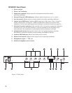
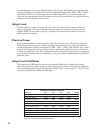
Figure 4. Internal view of mixer.
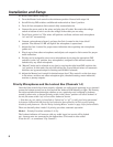
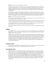
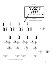
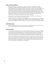
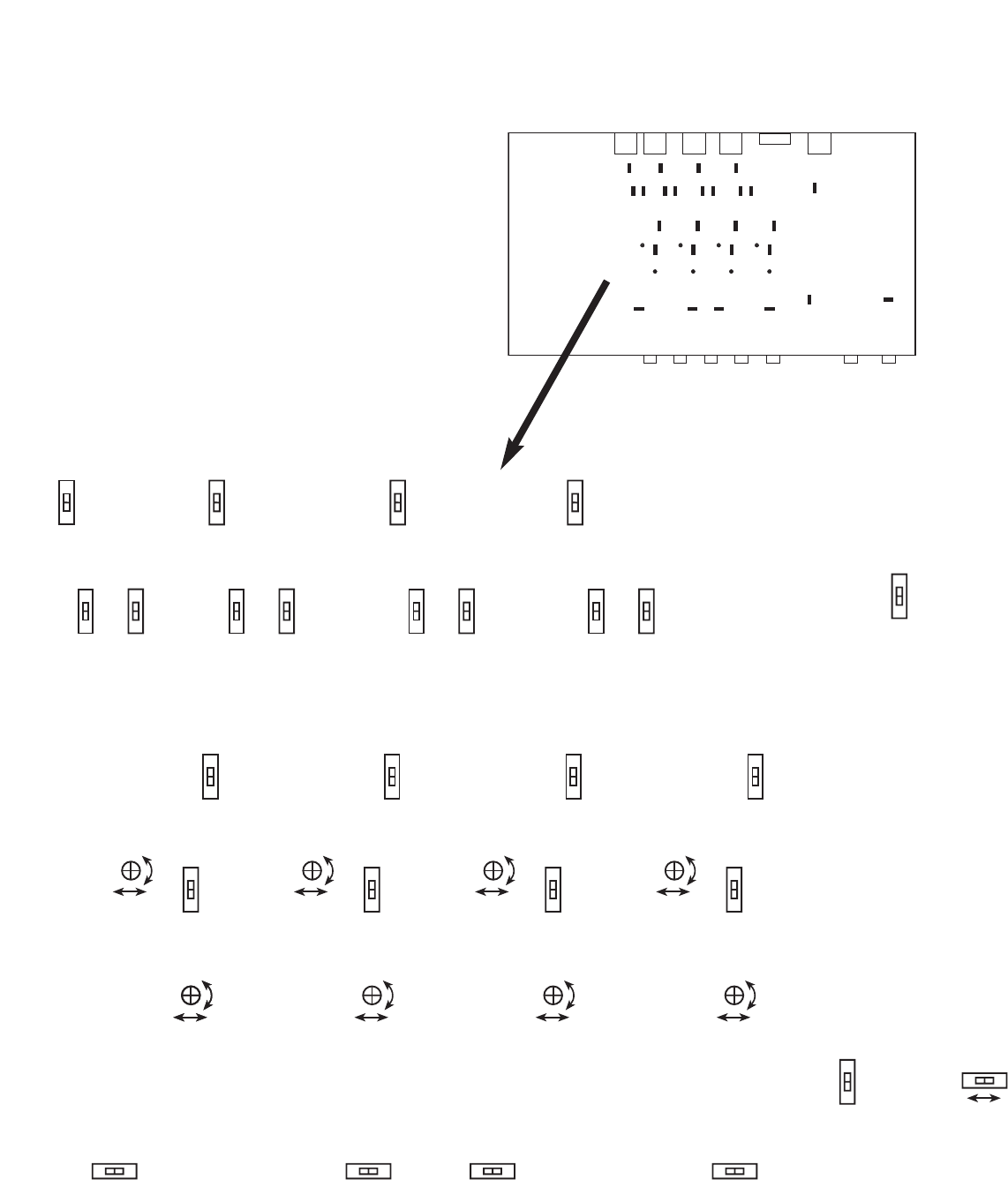
Figure 5. Detail of internal controls.
SW27
SW25
SW26
Front Panel
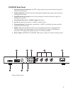
Rear Panel
11
Mic
Line
SW3
–40 dB
SW5
–20 dB
VR3
Min. –6 dB
–40 dB
SW1 1
–20 dB
VR6
Min. –6 dB
–40 dB
SW1 7
–20 dB
VR9
Min. –6 dB
–40 dB
SW23
–20 dB
VR1 2
Min. –6 dB
–1 0 dB +10 dB
VR2
–1 0 dB +10 dB
VR2
–1 0 dB +10 dB
VR5
–1 0 dB + 10 dB
VR8
–1 0 dB + 10 dB
VR1 1
Phantom
Of f
SW1
30 dB
SW2
40 dB Phantom
Of f
SW7
30 dB
SW8
40 dB Phantom
Of f
SW13
30 dB
SW14
40 dB Phantom
Of f
SW19
30 dB
SW20
40 dB
SW22
Of f O n
SW4
Of f O n
SW10
Of f O n
SW16
Of f O n
SW27
Pe ak RMS
Meter
Of f
On
SW25NOMA
Line
Mic
Outpu t
SW26
Mic
Line
SW9
Mic
Line
SW1 5
Mic
Line
SW21
SW6 SW12 SW18 SW2 4
Gatin g
Of f
Gatin g
Of f
Gatin g
Of f
Gatin g
Of f