


4
THERMOSTAT INSTALLATION (MODEL 2H2C)
FURNACE - MODEL 2540 MUST USE THIS THERMOSTAT
The thermostat is very sensitive. HANDLE WITH CARE AT ALL TIMES.
Locate thermostat 48˝ to 54˝ above floor on an INTERIOR wall. Pick a dry
area where air circulation is good. EXTERIOR wall location must have a
3/4˝ spacer between thermostat and exterior wall.
1. Be sure all electrical power has been disconnected from the air con-
ditioner, furnace and the power supply.
2. Do not install the thermostat where there are unusual heating condi-
tions: such as direct sunlight, heat producing appliances (television,
radio, wall lamp, etc.) or a furnace or air conditioner supply register.
3.
ATTACHING THE WALL THERMOSTAT. Separate the thermostat body from the
sub-base by gently squeezing the top and bottom. Pull wires through
access hole in base plate. Attach thermostat sub-base to the wall at
the desired mounting location. Mount the sub-base to the wall before
connecting the wires. See instruction provided with thermostat.
SYSTEM CHECKS
ƽ WARNING
FIRE OR EXPLOSION
• Never check for leaks with an open flame.
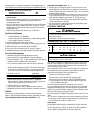
DIAGNOSTIC CHART
A diagnostic LED is located inside the exterior access cover on the out-
side edge of the horizontal (2) stage control board. The following
graph defines the codes.
NUMBER OF LED FLASHES DIANOSTIC INFORMATION LOCKOUT
1 Low Input voltage SOFT
2 Ignition Failure SOFT
3 Open High Limit SOFT
4 Stuck Sail Switch HARD
5 Module Fault HARD
NOTE:A SOFT lockout is a condition that is timed and will make addition-
al attempts to correct the problem. A HARD lockout requires reset
of the thermostat or turning the power switch off then back on.
PROPANE GAS PRESSURE TEST
The furnace and any individual shut-off valve must be disconnected
from gas supply piping system during any pressure testing of system
at test pressures of more than 1/2 PSI.
Before furnace is connected piping systems must be tested to be leak
free. The test must maintain air pressure of at least 6˝ of mercury or 3
PSI for at least 10 minutes.
The entire piping system must be maintained within a range of 10-14˝
W.C. when all appliances are in operation. Test gas connections for
leakage with a leak test solution.
STATIC PRESSURE TEST
CASING STATIC PRESSURE TABLE
If duct static pressure cannot be set, casing static pressure should not exceed
the values listed below when taken cold.
DUCTING SYSTEM OPERATING VOLTS FLEXIBLE HARD
DC MODELS 12 0.25˝ W.C. 0.35˝ W.C.
Voltage greater than indicated will cause higher static readings.
Reducing the number of duct turns and stretching ducts will increase
air flow and reduce static pressure. Adding ducts or increasing dis-
charge system (hard ducting) will also reduce static pressure. NOTE:
Special tool required to take casing static pressures.
Location for Static Pressure Tap for casing is on the back of casing
(top left corner) (
FIG 3).
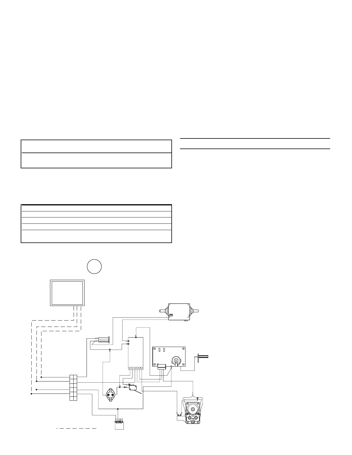
VALVE
MOTOR
IGNITION
CONTROL
SAIL
SWITCH
+12 VDC
-12 VDC
YELLOW
LIMIT
SWITCH
BULK HEAD
CONNECTOR
DUAL
CONTROL
WHITE
YELLOW
YELLOW
BLUE
ORANGE
BROWN
BLACK
BLACK
BLUE
RED
RED
HIGH TENSION
CHASSIS
GROUND
CHASSIS
GROUND
ELECTRODE
RED
RED
WHITE
GREEN
+THERMO
-THERMO
ELECTRONIC
DIGITAL
THERMOSTAT
1
1
1
22
2
3
3
3
4
4
4
5
5
5
66
6
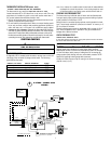
CUSTOMER SUPPLIED WIRE
IMPORTANT: If any original wire has to
be replaced, it must be replaced with
type 105˚C or it's equivalent.
2-STAGE - MODEL 2540
WIRING
4