


2
Spacing of 1/4˝ to ducting within 3 feet of furnace must be provided
unless UL listed wire bound vinyl ducts are used. All ducting material
should be rated for continuous use at 200˚F.
NOTE: Clearances are specifically for plywood or similar building materi-
als surrounding the furnace (i.e. furnace should
NOT be located
under furniture or in a closet space where clothing or other mate-
rial could be located.)
NOTE: Furnace efficiency rating is a thermal rating determined under
continuous operating conditions, independent of any installation.
Efficiency rate is given at 77% minimum, actual efficiency rating
may be higher.
ƽ WARNING
CARBON MONOXIDE POISONING
• Furnace must be installed and vented to these instructions.
• Improper installation, adjustment, alteration, service or mainte-
nance can cause injury or property damage.
• Improper installation location may cause furnace to produce neg-
ative pressure, affecting combustion air or venting of other appli-
ances.
ƽ CRITICAL INSTALLATION WARNINGS
• DO NOT install furnace on material that restricts return air, such as
carpeting or any soft material i.e. vinyl.
• DO NOT install furnace where clearance to combustibles cannot be
maintained.
• DO NOT modify furnace in any way.
• Installation must provide accessibility if any repairs are necessary to
the furnace. Failure to meet this requirement will create additional
labor costs that will be the responsibility of the installer.
• DO NOT alter furnace for a positive grounding system.
• DO NOT HI-POT furnace unless electronic ignition system (circuit
board) has been disconnected.
• DO NOT use battery charger to supply power to DC model furnace
even when testing.
• DO NOT use 120 volt AC current with DC models.
• DO NOT use furnace cabinet area as a storage compartment.
• DO NOT vent furnace with venting system serving another appliance.
• DO NOT vent furnace to an outside enclosed porch area.
• DO NOT use for temporary heating of buildings or structures under
construction.
• Protect building materials from degrading from flue gas exhaust.
• Protect furnace electrical components from water.
USA AND CANADA - FOLLOW ALL APPLICABLE STATE AND LOCAL CODES -
IN THE ABSENCE OF LOCAL CODES OR REGULATIONS, REFER TO CURRENT STANDARDS OF:
• Recreation Vehicles ANSI A119.2/NFPA 501C.
• National Fuel Gas Code ANSI Z223.1 and/or CAN/CGA B149
Installation Codes
• Federal Mobile Home Construction & Safety Standard, Title 24 CFR,
part 3280, or when this Standard is not applicable, the Standard for
Manufactured Home Installations (Manufactured Home Sites,
Communities and Set-Ups), ANSI A255.1 and/or CAN/CSA-Z240 MH
Series, Mobile Homes.
•
Ground-National Electrical Code ANSI/NFPA No. 70 and/or CSA C22.1
• Park Trailers ANSI A119.5
NOTE: The direct high voltage spark ignition generates a radio frequency
that could cause interference with other microprocessor based
equipment. Locate equipment at least five feet (5’) from furnace
location. If this distance cannot be maintained, purchase KIT
MPD 37773 (a shielded high voltage lead).
ƽ WARNING
CARBON MONOXIDE POISONING
•
Properly seal vent assembly to prevent carbon monoxide from
entering coach.
• DO NOT draw combustion air from living area. DO NOT vent exhaust
air into the living area or an enclosed porch.
Return air is supplied through openings in furnace casing. All return
air passages must be kept clear for furnace to function properly. Refer
to
MINIMUM CLEARANCE TO FLOORBOARDS, WALLS & SIMILAR COMBUSTIBLE BUILDING
MATERIAL
. The total unobstructed return air opening size(s) must NOT BE
LESS than specified in SPECIFICATIONS - MINIMUM RETURN AIR. Failure to meet
minimum return air requirements nullifies furnace warranty.
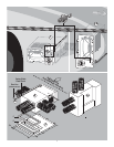
STANDARD FURNACE INSTALLATION
General Installation -
LOCATION
• Install furnace through an exterior wall.
• DO NOT install furnace near tilt-out rooms, slide-outs, doors or
other projections that could obstruct furnace exhaust.
• Locate furnace near midpoint of coach for single furnace applications.
• DO NOT install vent in areas where projections or door openings
are within 6˝ of vent tube opening.
• DO NOT install furnace in an area where wires, pipes, or other
objects will interfere with installation or operation of furnace.
• It is not recommended to install furnace on material that restricts
return air, such as carpeting, or soft material such as vinyl.
• DO NOT directly install furnace on carpeting or soft material, install
furnace on cleats, or on a wood or metal panel extending the full
width and depth of furnace plus minimum clearances to combustibles.
• DO NOT use petroleum or citrus type cleaners on plastic parts, as
damage may occur.
• The furnace must always be installed level (front to back, side to
side) to prevent water intrusion into the interior.
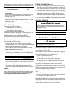
WALL CUTOUT OPTIONS HORIZONTAL & VERTICAL
RECOMMENDED WALL THICKNESS
0˝ to 2-1/2˝
DO NOT OVERSIZE HOLE - OVERSIZING CAN RESULT IN WATER LEAKAGE
EXTERIOR WALL CUTOUT (FIG 1 -1A) ABC
HORIZONTAL & VERTICAL 3-1/8˝ 2-3/8˝ 3-1/2˝ dia. hole
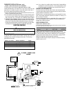
VENT INSTALLATION HORIZONTAL & VERTICAL INSTALLATION (FIG 1-1A)
1. Locate vent hole cutout as called out in
FIG 1-1A.
2. Drill 3-1/2˝ diameter hole through side wall of coach.
3. Remove vent and vent ring from furnace.
4. Insert furnace from backside of wall. Line up hole in wall with hole
for vent to furnace.
5. Apply sealant to back of vent ring and vent cap base.
6. Install vent assembly with HOT at top for horizontal and on right
side for vertical installation (
FIG 1-1A). Slip into combustion air
intake tube. Secure to wall with four (4) screws.
7. Vent assembly must have a minimum of 1-1/4˝ overlap on exhaust
and 1/2˝ minimum on combustion air.
8. Horizontal units - secure to floor with two (2) screws through legs
on back of casing. Vertical units use vertical mounting brackets and
self-tapping screws to hold furnace to floor (tabs on control box can
be used also to secure furnace).
DUCTING HORIZONTAL & VERTICAL (FIG 2-3A)
HORIZONTAL
PROPER DUCT INSTALLATION IS CRITICAL TO THE OPERATION OF THIS FURNACE
CONTINUOUS USE MATERIALS RATING
DUCTS 9˝ IN LENGTH OR MORE 200˚F.
4˝ DUCTS -LESS THAN 9˝ IN LENGTH 250˚F.
METAL BOOTS LESS THAN
9˝ IN LENGTH
250˚F.